Content for TS 23.502 Word version: 19.2.0
1…
4.2.2.2.2
4.2.2.2.3…
4.2.2.3…
4.2.3…
4.2.3.3
4.2.4…
4.2.6
4.2.7…
4.2.9…
4.2.11…
4.2.11.5…
4.3…
4.3.2.2.2
4.3.2.2.3…
4.3.3…
4.3.3.3
4.3.4…
4.3.4.3
4.3.5…
4.3.5.2…
4.3.5.4…
4.3.5.6…
4.3.6…
4.4…
4.5…
4.9…
4.9.1.3…
4.9.2…
4.11…
4.11.1…
4.11.1.2.2
4.11.1.2.3
4.11.1.3…
4.11.1.3.3…
4.11.1.4…
4.11.1.5…
4.11.2…
4.11.3…
4.12…
4.12.6…
4.12a…
4.12b…
4.13…
4.13.4…
4.13.6…
4.14…
4.15…
4.15.3.2.5…
4.15.4…
4.15.6…
4.15.6.7…
4.15.6.13…
4.15.6.14…
4.15.9…
4.15.9.4…
4.15.13…
4.15.13.4…
4.16…
4.16.4…
4.16.8…
4.16.11…
4.16.14…
4.16.15…
4.17…
4.17.9…
4.18…
4.19…
4.22…
4.23…
4.23.7…
4.23.7.3.3
4.23.7.3.4…
4.23.9…
4.23.9.4…
4.23.11…
4.24…
4.25…
4.25.6…
4.26…
5…
5.2.3…
5.2.5…
5.2.6…
5.2.7…
5.2.8…
5.2.9…
5.2.12…
5.2.18…
A…
E…
F…
G
H…
F Information flows for 5GS integration with TSN or with Deterministic Networking
F.1 5GS Bridge information reporting
F.2 5GS Bridge configuration
F.3 BMCA procedure
F.4 5GS interworking with TSN deployed in the transport network
F.5 5GS DetNet node information reporting
F.6 5GS DetNet node configuration
...
...
F Information flows for 5GS integration with TSN or with Deterministic Networking |R16| p. 900
This Annex defines the procedures for 5GS integration with TSN fully-centralized model as defined in IEEE Std 802.1Q [66], it includes 5GS Bridge information reporting and 5GS Bridge configuration.
The Annex defines also the procedures for 5GS interworking with the TSN deployed in the transport network, as described in clause 5.28a of TS 23.501.
F.1 5GS Bridge information reporting p. 900
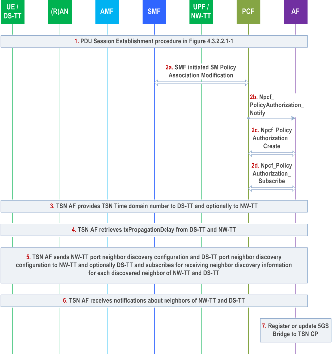
Identities of 5GS Bridge and UPF/NW-TT ports are pre-configured on the UPF based on deployment. The SMF requests the UPF/NW-TT to measure and report the clock drift between the TSN GM time and 5GS GM time for one or more TSN time domains.
Step 1.
PDU Session Establishment as defined clause 4.3.2.2.1 is used to establish a PDU Session serving for TSC.
During this procedure, the SMF selects a UPF, which supports functions as defined in clause 5.28.1 of TS 23.501, for the PDU Session.
During this procedure, the SMF receives the UE-DS-TT residence time, DS-TT MAC address for this PDU Session and port management capabilities from the DS-TT/UE in PDU Session Establishment request and receives the allocated port number for DS-TT Ethernet port and user-plane Node ID in N4 Session Establishment Response message. The UPF allocates the port number for DS-TT, user-plane Node ID after receiving N4 Session Establishment Request message.
Step 2.
The SMF sends the information received in step 1 to the TSN AF via PCF to establish/modify the 5GS Bridge. The Npcf_PolicyAuthorization_Notify message in step 2b is delivered via the pre-configured AF session as described in clause 4.16.5.1. The TSN AF stores the binding relationship between 5GS user-plane Node ID, MAC address of the DS-TT Ethernet port and also updates 5GS bridge delay as defined in clause 5.27.5 of TS 23.501 for future configuration. The TSN AF requests creation of a new AF session associated with the MAC address of the DS-TT Ethernet port using the Npcf_PolicyAuthorization_Create operation (step 2c) and subscribes for TSN events over the newly created AF session using the Npcf_PolicyAuthorization_Subscribe operation (step 2d).
In the case of TSN AF support for direct notification from UPF for PMIC and UMIC, the subscription in step 2d has following additional information: "Notification Target Address for PMIC/UMIC UPF event" and "Correlation ID for PMIC/UMIC UPF event".
Using the 5GS user-plane Node ID received in step 2b the TSN AF subscribes with the NW-TT for receiving user plane node management information changes for the 5GS bridge indicated by the 5GS user-plane Node ID as described in clause 5.28.3.1 of TS 23.501.
After receiving a User plane node Management Information Container (UMIC) containing the NW-TT port numbers, the TSN AF subscribes with the NW-TT for receiving NW-TT port management information changes for the NW-TT port indicated by each of the NW-TT port numbers as described in clause 5.28.3.1 of TS 23.501.
The TSN AF can use any PDU Session to subscribe with the NW-TT for bridge or port management information notifications. Similarly, the UPF can use any PDU Session to send bridge or port management information notifications.
Step 3.
If DS-TT has indicated support for the TSN Time domain number in the port management capabilities, TSN AF provides the TSN Time domain number to DS-TT. Optionally, TSN AF provides the TSN Time domain number to NW-TT.
Step 4.
If supported according to the port management capabilities received from DS-TT, TSN AF retrieves txPropagationDelay and Traffic Class table from DS-TT. TSN AF also retrieves txPropagationDelay and Traffic Class table from NW-TT.
Step 5.
If DS-TT supports neighbor discovery according to the port management capabilities received from DS-TT, then TSN AF:
Step 6.
- provides DS-TT port neighbor discovery configuration to DS-TT to configure and activate the LLDP agent in DS-TT;
- subscribes to receive Neighbor discovery information for each discovered neighbor of DS-TT (see Table K.1-1 in TS 23.501.
- provides DS-TT port neighbor discovery configuration to NW-TT to configure and activate the LLDP agent in NW-TT to perform neighbor discovery on behalf of DS-TT;
- subscribes to receive Neighbor discovery information for each discovered neighbor of DS-TT from NW-TT (see Table K.1-1 in TS 23.501.
- writes NW-TT port neighbor discovery configuration to NW-TT to configure and activate the LLDP agent in NW-TT;
- subscribes to receive Neighbor discovery information for each discovered neighbor of NW-TT (see Table K.1-1 in TS 23.501).
TSN AF receives notifications from DS-TT (If DS-TT supports neighbour discovery) and NW-TT on discovered neighbors of DS-TT and NW-TT.
Step 7.
The TSN AF constructs the above received information as 5GS Bridge information and sends them to the CNC to register a new TSN Bridge or update an existing TSN Bridge.
F.2 5GS Bridge configuration p. 902
For 5GS integrating with fully-centralized model TSN network, the CNC provides TSN information to the AF.
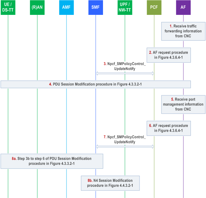
Step 1.
If the UPF sends a Clock Drift Report to the SMF as described in clause 5.27.2 of TS 23.501, the SMF adjusts the Burst Arrival Time, Periodicity and Survival Time (if present) from a TSN grandmaster clock to the 5G clock and sends the updated TSCAI to NG-RAN.
CNC provides per-stream filtering and policing parameters according to section 8.6.5.2.1 of IEEE Std 802.1Q [66] to AF and the AF uses them to derive TSN QoS information and related flow information. The CNC provides the forwarding rule to AF according to section 8.8.1 of IEEE Std 802.1Q [66]. The TSN AF uses this information to identify the DS-TT MAC address of corresponding PDU session.
The AF determines if the stream is UE-UE TSC and divides the stream into UL and DL streams for PDU Sessions corresponding to ingress DS-TT Ethernet port and egress DS-TT port(s) as specified in clause 5.28.2 of TS 23.501 and separately triggers following procedures for the UL and DL streams.
Step 2.
The AF determines the MAC address of a PDU Session based on the previous stored associations, then triggers an AF request procedure. The AF request includes the DS-TT MAC address of the PDU session.
Based on the information received from the CNC, 5GS bridge delay information and the UE-DS-TT residence time, the TSN AF determines the TSN QoS information and TSC Assistance Container for one or more TSN streams and sends them to the PCF. The TSN AF also provides Service Data Flow Filter containing Flow description also includes Ethernet Packet Filters.
Step 3.
When PCF receives the AF request, the PCF finds the correct SMF based on the DS-TT MAC address of the PDU session and notifies the SMF via Npcf_SMPolicyControl_UpdateNotify message.
After mapping the received TSN QoS parameters for TSN streams to 5GS QoS, the PCF triggers Npcf_SMPolicyControl_UpdateNotify message to update the PCC rule to the SMF. The PCC rule includes the Ethernet Packet Filters, the 5GS QoS profile along with TSC Assistance Container.
Step 4.
SMF may trigger the PDU Session Modification procedure to establish/modify a QoS Flow to transfer the TSN streams. During this procedure, the SMF provides the information received in PCC rules to the UPF via N4 Session Modification procedure.
Upon reception of the TSC Assistance Container, the SMF determine the TSCAI for QoS flow and sends the TSCAI along with the QoS profile to the NG RAN.
Step 5.
If needed, the CNC provides additional information (e.g. the gate control list as defined in section 8.6.8.4 of IEEE Std 802.1Q [66]) to the TSN AF.
Step 6.
The AF determines the MAC address of a PDU Session for the configured port based on the previous stored associations, this is used to deliver the Port Management information to the correct SMF that manages the port via PCF. The AF triggers an AF request procedure. The AF request includes the DS-TT MAC address (i.e. the MAC address of the PDU Session), TSN QoS Parameters, Port Management information Container and the related port number as defined in clause 5.28.3 of TS 23.501. The port number is used by SMF to decide whether the configured port is in DS-TT or NW-TT.
Step 7.
The PCF determines the SMF based on the MAC address received in the AF request, the PCF maps the TSN QoS information provided by the AF to PCC rules as described in clause 5.28.4 of TS 23.501. The PCF includes the TSC Assistance Container received from the AF with the PCC rules and forwards it to the SMF. The PCF transparently transports the received Port Management information Container and related port number to SMF via Npcf_SMPolicyControl_UpdateNotify message.
Step 8a.
If the SMF decides the port is on DS-TT based on the received port number, the SMF transports the received Port Management information Container to the UE/DS-TT in PDU Session Modification Request message.
Step 8b.
If the SMF decides the port is on NW-TT based on the received port number, the SMF transports the received Port Management information Container to the UPF/NW-TT in N4 Session Modification Request message. SMF provides the Ethernet Packet Filters as part of the N4 Packet Detection rule to the UPF/NW-TT.
F.3 BMCA procedure |R17| p. 903
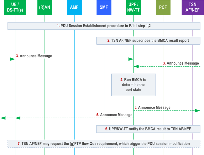
Step 1.
PDU Session Establishment is performed as shown in Figure F.1-1 step 1 and 2 for an Ethernet or IP type PDU Session to carry the UMIC or PMIC.
Step 2.
The TSN AF or TSCTSF may subscribe to notifications for the PTP port state changes from UPF/NW-TT.
Step 3.
The UPF/NW-TT receives the Announce message via User -plane from DS-TT connectivity established using PDU session, or via NW-TT port over N6.
As Announce message is a periodic message, after step 3, the UPF/NW-TT will receive Announce messages regularly.
Step 4.
The NW-TT runs the BMCA algorithm in order to determine the PTP port state for the DS-TT port(s) and NW-TT port(s).
BMCA will be triggered after receiving the Announce message.
Step 5.
If the BMCA procedure in NW-TT determines to use Announce message from the external grandmaster PTP instance, the UPF/NW-TT regenerates the Announce message based on the received Announce message for each Leader PTP port on the NW-TT and DS-TT(s) port for this PTP domain. The NW-TT/UPF forwards the regenerated Announce messages to the PDU session(s) related to the Leader PTP ports on the DS-TT(s).
Step 6.
If the TSN AF or TSCTSF has subscribed for notifications for the PTP port state changes, the UPF/NW-TT reports any changes to the PTP port states to the TSN AF or TSCTSF via UMIC (for DS-TT ports) or PMIC (for NW-TT ports).
Step 7.
Based on the notification for the PTP port state changes, the TSN AF or TSCTSF may request appropriate QoS treatment and PDU Session modification may then be triggered to modify the QoS Flow carrying the gPTP messages over user plane in order to be compliant with the IEEE Std 802.1AS [75] delay recommendation for carrying gPTP messages as in clause 5.27.1.6 of TS 23.501.
F.4 5GS interworking with TSN deployed in the transport network |R18| p. 904
For 5GS to control the IEEE TSN features deployed in the transport network, the SMF/CUC interacts with the CNC in the transport network (TN CNC).
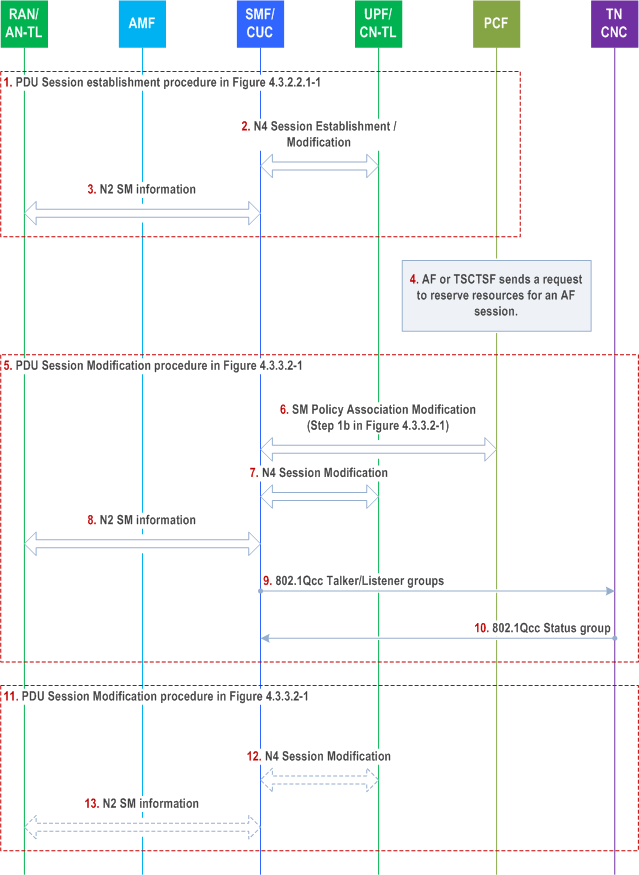
Step 1.
The UE establishes a PDU Session as described in clause 4.3.2.2.1.
Step 2.
During the PDU Session Establishment procedure, the SMF/CUC requests the UPF to assign the N3 tunnel information via N4 Session Establishment or Modification procedure. If interworking with TSN deployed in the transport network is supported (see clause 4.4.8 of TS 23.501), and the UPF supports CN-TL, the SMF/CUC includes a TL-Container to the N4 Session Establishment or Modification request including a get-request to the TL-Container, as described in clause 5.28a.2 of TS 23.501.
The UPF responds with a N4 Session Establishment or Modification response. If the UPF supports CN-TL, the UPF includes a TL-Container to the response. The TL-Container includes a get-response as described in clause 5.28a.2 of TS 23.501. The SMF/CUC stores the information provided in the get-response.
Step 3.
During the PDU Session Establishment procedure, the SMF/CUC requests the NG-RAN to assign the N3 tunnel information by invoking the Namf_Communication_N1N2MessageTransfer request. The SMF/CUC includes a TL-Container to the N2 SM information in the request, the TL-Container contains a get-request as described in clause 5.28a.2 of TS 23.501.
The NG-RAN responds with a N2 SM information. If the NG-RAN supports AN-TL, the NG-RAN includes a TL-Container to the N2 SM information. The TL-Container includes a get-response as described in clause 5.28a.2 of TS 23.501. The SMF/CUC stores the information provided in the get-response.
Step 4.
The AF (TSCTSF, AF, NEF or TSN AF) invokes the Npcf_PolicyAuthorization_Create /Update request. This may be due to reception of Ntsctsf_QoSandTSCAssistance_Create /Update request by the TSCTSF as described in clause 4.15.6.6 or clause 4.15.6.6a, or due to reception of 5GS Bridge configuration by the TSN AF as described in clause F.2. The TSN AF or TSCTSF determines the TSC Assistance Container for one or more TSC streams and sends them to the PCF.
Step 5-6.
When PCF receives the request, the PCF initiates an SM Policy Association Modification procedure. The PCF notifies the corresponding SMF/CUC via Npcf_SMPolicyControl_UpdateNotify message as described in clause 4.16.5.2. The PCF updates the PCC rule to the SMF/CUC. The PCC rule includes the 5GS QoS profile along with TSC Assistance Container.
SMF/CUC triggers the PDU Session Modification procedure as described in clause 4.3.3.2 to establish a QoS Flow to transfer the TSC streams.
Step 7.
During the PDU Session Modification procedure, the SMF/CUC provides the information received in PCC rules to the UPF via N4 Session Modification procedure. The SMF/CUC may instruct the UPF to assign a distinct N3 tunnel end point address for the QoS Flow as described in clause M.1 of TS 23.501.
The UPF responds with a N4 Session Modification response.
Step 8.
During the PDU Session Modification procedure, the SMF/CUC provides the information received in PCC rules to the NG-RAN by invoking the Namf_Communication_N1N2MessageTransfer request. The SMF also determines the TSCAI for the QoS Flow(s) and sends the TSCAI along with the QoS profile(s) to the NG-RAN. The SMF/CUC may instruct the NG-RAN to assign a distinct N3 tunnel end point address for the QoS Flow as described in clause M.1 of TS 23.501.
The NG-RAN responds with a N2 SM information.
Step 9.
The SMF/CUC determines the merged stream requirements in the TSN UNI towards the TN CNC as described in Annex M of TS 23.501. The TN CNC uses the merged stream requirements as input to select respective path(s) and calculate schedules in TN.
Step 10.
Based on the results, the TN CNC provides a Status group that contains the merged end station communication-configuration back to the SMF/CUC.
Step 11.
[Conditional] If the response from TN CNC includes InterfaceConfiguration, the SMF/CUC triggers the PDU Session Modification procedure as described in clause 4.3.3.2 to modify the QoS Flow to transfer the TSC streams.
Step 12.
[Conditional] During the PDU Session Modification procedure, if the UPF supports CN-TL, the SMF/CUC invokes N4 Session Modification procedure and includes TL-Container(s) to the N4 Session Modification request including a set-request to the TL-Container as described in clause 5.28a.2 of TS 23.501.
The UPF responds with a N4 Session Modification response. If the UPF supports CN-TL, the UPF includes a TL-Container to the response. The TL-Container includes a set-response as described in clause 5.28a.2 of TS 23.501.
Step 13.
[Conditional] During the PDU Session Modification procedure, if the NG-RAN supports AN-TL, the SMF/CUC invokes the Namf_Communication_N1N2MessageTransfer request. The SMF/CUC includes TL-Container(s) to the N2 SM information in the request, the TL-Container contains a set-request as described in clause 5.28a.2 of TS 23.501. The SMF/CUC may also update the TSCAI in the NG-RAN for the BAT in DL direction as described in Annex M, clause M.1 of TS 23.501, if the SMF/CUC received a TimeAwareOffset or AccumulatedLatency from TN CNC for a downlink stream (i.e. for a Talker in the UPF/CN-TL) in step 7.
The NG-RAN responds with a N2 SM information. If the NG-RAN supports AN-TL, the NG-RAN includes TL-Container(s) to the N2 SM information. The TL-Container includes a set-response as described in clause 5.28a.2 of TS 23.501.
F.5 5GS DetNet node information reporting |R18| p. 907
The TSCTSF collects the information for Deterministic Networking from the UPF/NW-TT and the SMF as shown in Figure F.5-1, with the addition of new parameters as shown in Figure F.5-1.
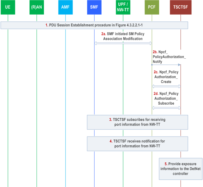
Step 1.
PDU Session Establishment as defined in clause 4.3.2.2.1 is used to establish a PDU Session. When Framed Routes applies, the SMF reports to the PCF Framed Route information.
Step 2.
SMF reports device port related information to PCF. When prefix delegation applies, the SMF reports to the PCF prefixes delegated to the UE by IPv6 prefix delegation. The PCF notifies TSCTSF of the Bridge/Router information. The TSCTSF subscribes for notifications on the Bridge/Router information and also subscribes for notifications on Reporting of extra addresses, so that the TSCTSF is notified when the SMF has reported to the PCF the Framed Route information or prefixes delegated to UE via IPv6 prefix delegation corresponding to the PDU Session.
Step 3-4.
Using the 5GS user-plane Node ID received in step 2b the TSCTSF can subscribe with the NW-TT for receiving user plane node management information changes for the 5GS router indicated by the 5GS user-plane Node ID in case it does not yet have such a subscription, as described in clause 5.28.3.1 of TS 23.501.
After receiving a User plane node Management Information Container (UMIC) containing the NW-TT port numbers, the TSCTSF can subscribe with the NW-TT for receiving NW-TT port management information changes for the NW-TT port indicated by each of the NW-TT port numbers as described in clause 5.28.3.1 of TS 23.501.
The TSCTSF can use any PDU Session to subscribe with the NW-TT for node or port management information notifications. Similarly, the UPF can use any PDU Session to send bridge or port management information notifications.
Step 5.
The TSCTSF may provide collected exposure information to the DetNet controller. The information being reported to the DetNet controller is defined in clause 5.28.5.2 of TS 23.501.
F.6 5GS DetNet node configuration |R18| p. 907
The DetNet controller triggers the procedure to provide Deterministic Networking specific parameters to 5GS.
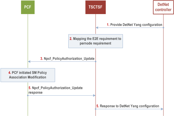
Step 1.
The DetNet controller provides YANG data model configuration to the TSCTSF. The TSCTSF uses the identifier of the incoming and outgoing interfaces to determine the affected PDU Session(s) and flow direction, whether it is uplink or downlink as described in more detail in clause 5.28.5 of TS 23.501. The TSCTSF also determines if the flow is UE to UE in which case two PDU Sessions will be affected for the flow and the TSCTSF breaks up the requirements to individual requirements for the PDU Sessions.
Step 2.
The TSCTSF uses the traffic requirements in the YANG configuration as described in clause 6.1.3.23b of TS 23.503. The TSCTSF also constructs the TSCAC for each flow description.
Step 3.
The TSCTSF provides the mapped parameters and the flow description to the PCF(s) on a per AF Session basis.
Step 4.
The PCF authorizes the request from TSCTSF. If the PCF determines that the requirements can't be authorized, it rejects the request. Once the PCF authorizes the request, the PCF updates the SMF with corresponding new PCC rule(s) with PCF initiated SM Policy Association Modification procedure as described in clause 4.16.5.2.
The SMF applies the received PCC rules. This can induce creating a new QoS flow to the PDU session and triggers the resource allocation in the RAN.
Step 5.
PCF provides response to the TSCTSF.
Step 6.
The TSCTSF provides response to the DetNet controller.