Content for TS 23.502 Word version: 19.2.0
1…
4.2.2.2.2
4.2.2.2.3…
4.2.2.3…
4.2.3…
4.2.3.3
4.2.4…
4.2.6
4.2.7…
4.2.9…
4.2.11…
4.2.11.5…
4.3…
4.3.2.2.2
4.3.2.2.3…
4.3.3…
4.3.3.3
4.3.4…
4.3.4.3
4.3.5…
4.3.5.2…
4.3.5.4…
4.3.5.6…
4.3.6…
4.4…
4.5…
4.9…
4.9.1.3…
4.9.2…
4.11…
4.11.1…
4.11.1.2.2
4.11.1.2.3
4.11.1.3…
4.11.1.3.3…
4.11.1.4…
4.11.1.5…
4.11.2…
4.11.3…
4.12…
4.12.6…
4.12a…
4.12b…
4.13…
4.13.4…
4.13.6…
4.14…
4.15…
4.15.3.2.5…
4.15.4…
4.15.6…
4.15.6.7…
4.15.6.13…
4.15.6.14…
4.15.9…
4.15.9.4…
4.15.13…
4.15.13.4…
4.16…
4.16.4…
4.16.8…
4.16.11…
4.16.14…
4.16.15…
4.17…
4.17.9…
4.18…
4.19…
4.22…
4.23…
4.23.7…
4.23.7.3.3
4.23.7.3.4…
4.23.9…
4.23.9.4…
4.23.11…
4.24…
4.25…
4.25.6…
4.26…
5…
5.2.3…
5.2.5…
5.2.6…
5.2.7…
5.2.8…
5.2.9…
5.2.12…
5.2.18…
A…
E…
F…
G
H…
4.3.5.4 Addition of additional PDU Session Anchor and Branching Point or UL CL
4.3.5.5 Removal of additional PDU Session Anchor and Branching Point or UL CL
...
...
4.3.5.4 Addition of additional PDU Session Anchor and Branching Point or UL CL p. 189
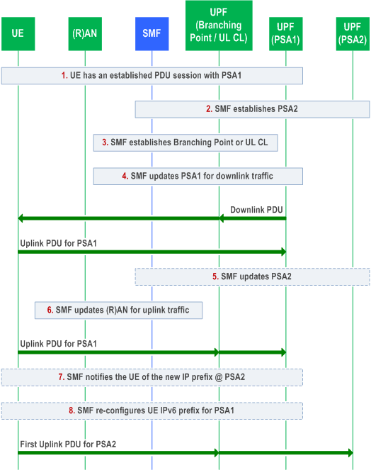
Clause 4.3.5.4 describes a procedure to add a PDU Session Anchor and a Branching Point or UL CL for an established PDU Session.

Step 1.
UE has an established PDU Session with a UPF including the PDU Session Anchor 1 (PSA1 in Figure 4.3.5.4-1). The PDU Session User Plane involves at least the (R)AN and the PDU Session Anchor 1.
Step 2.
At some point the SMF decides to establish a new PDU Session Anchor e.g. due to UE mobility, new flow detection. The SMF selects a UPF and using N4 establish the new PDU Session Anchor 2 (PSA2 in Figure 4.3.5.4-1) of the PDU Session. In the case of IPv6 multi-homing PDU Session, the SMF also ensures that a new IPv6 prefix corresponding to PSA2 is allocated and if the PCF has subscribed to the IP allocation/release event, the SMF performs the Session Management Policy Modification procedure as defined in clause 4.16.5 to provide the new allocated IPv6 prefix to the PCF.
If the runtime coordination between 5GC and AF is enabled based on local configuration, according to the indication of "AF acknowledgment to be expected" is included in AF subscription to SMF events, the SMF sends an early notification to the AF after new PSA (PSA2 in Figure 4.3.5.4-1) is selected and waits for a notification response from the AF before configuring the new PSA. If the SMF receives a negative notification response from the AF, the SMF may stop the procedure.
Step 3.
The SMF selects a UPF and using N4 establish the Branching Point (in the case of IPv6 multi-homing) or a UL CL for the PDU Session. It provides the necessary uplink forwarding rules towards PSA1 and PSA2 including the PSA1 CN Tunnel Info and the PSA2 CN Tunnel Info. In addition, the AN Tunnel Info is provided for downlink forwarding. In the case of IPv6 multi-homing, the SMF also provides traffic filters for the IPv6 prefixes corresponding to PSA1 and PSA2 indicating what traffic shall be forwarded towards PSA1 and PSA2 respectively.
In the case of UL CL, the SMF provides traffic filters indicating what traffic shall be forwarded towards PSA1 and PSA2 respectively. If the runtime coordination between 5GC and AF is enabled based on local configuration, according to the indication of "AF acknowledgment to be expected" is included in AF subscription to SMF events, the SMF sends a late notification to the AF and waits for a notification response from the AF before configuring the UL CL. If the SMF receives a negative notification response from the AF, the SMF may stop the procedure.
Step 4.
The SMF updates the PSA1 via N4. It provides the Branching Point or UL CL CN Tunnel Info for the downlink traffic.
Step 5.
The SMF updates PSA2 via N4. It provides the Branching Point or UL CL CN Tunnel Info for down-link traffic.
Step 6.
The SMF updates (R)AN via N2 SM information over N11. It provides the new CN Tunnel Info corresponding to the UPF (Branching Point or UL CL). In the case of UL CL, if there is an existing UPF between the (R)AN and new inserted UL CL, the SMF updates the existing UPF via N4 instead of updating the (R)AN.
Step 7.
In the case of IPv6 multi-homing, the SMF notifies the UE of the availability of the new IP prefix @ PSA2. This is performed using an IPv6 Router Advertisement message (RFC 4861). Also, the SMF sends IPv6 multi-homed routing rule along with the IPv6 prefix to the UE using an IPv6 Router Advertisement message (RFC 4191) as described in clause 5.8.2.2.2 of TS 23.501.
If the runtime coordination between 5GC and AF is enabled based on local configuration, according to the indication of "AF acknowledgment to be expected" included in AF subscription to SMF events, the SMF sends a late notification to the AF and waits for a notification response from the AF before sending the new IP prefix to the UE. If the SMF receives a negative notification response from the AF, the SMF may stop the procedure.
Step 8.
In the case of IPv6 multi-homing, the SMF may re-configure the UE for the original IP prefix @ PSA1,i.e. SMF sends IPv6 multi-homed routing rule along with the IPv6 prefix to the UE using an IPv6 Router Advertisement message (RFC 4191) as described in clause 5.8.2.2.2 of TS 23.501.
4.3.5.5 Removal of additional PDU Session Anchor and Branching Point or UL CL p. 190
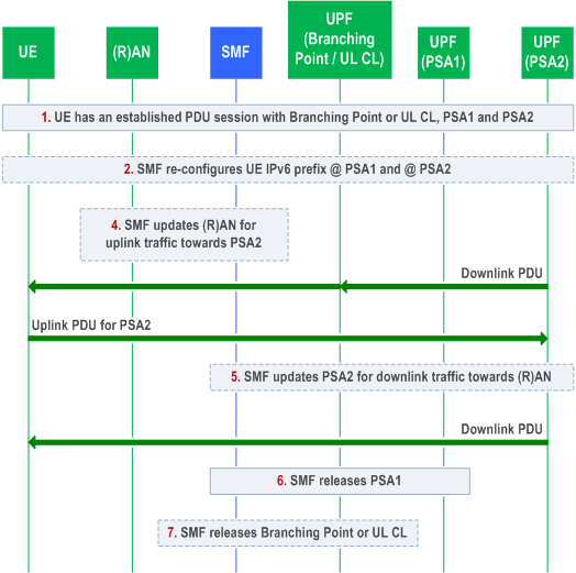
Clause 4.3.5.5 describes a procedure to remove a PDU Session Anchor and (optionally) remove Branching Point or UL CL for an established PDU Session.

Step 1.
UE has an established PDU Session with a UPF including the Branching Point or UL CL, the PDU Session Anchor 1 (PSA1 in Figure 4.3.5.5-1) and the PDU Session Anchor 2 (PSA2 in Figure 4.3.5.5-1).
At some point the SMF decides to remove the PDU Session Anchor 1 e.g. due to UE mobility, flow terminated.
Step 2.
In the case of IPv6 multi-homing, the SMF notifies the UE to stop using the IPv6 prefix corresponding to PSA1. This is performed by IPv6 Router Advertisement message (RFC 4861 and RFC 4862). Also, the SMF sends IPv6 multi-homed routing rule along with the IPv6 prefix corresponding to PSA2 to the UE as described in clause 5.8.2.2.2 of TS 23.501. Based on the information provided in the Router Advertisement, the UE starts using the IPv6 prefix (corresponding to PSA2) for all the traffic.
Step 4.
If the Branching Point or UL CL is to be released, the SMF updates the (R)AN with the PSA2 CN Tunnel Info. In the case of UL CL, if there is an existing UPF between the (R)AN and the UL CL to be removed, the SMF updates the existing UPF via N4 instead of updating the (R)AN.
Step 5.
If the Branching Point or UL CL is to be released, the SMF updates via N4 the PSA2 providing the AN Tunnel Info. In the case of UL CL, if there is an existing UPF between the (R)AN and the UL CL to be removed, the SMF updates the PSA2 providing the UPF CN tunnel Info.
Step 6.
The SMF releases via N4 the PSA1. In the case of IPv6 multi-homing, the SMF also releases the corresponding IPv6 prefix and if the PCF has subscribed to the IP allocation/release event, the SMF performs the Session Management Policy Modification procedure as defined in clause 4.16.5 to notify the PCF of the IPv6 prefix release.
Step 7.
If steps 4 and 5 were executed, the SMF releases the Branching Point / UL CL.