Content for TS 23.502 Word version: 19.2.0
1…
4.2.2.2.2
4.2.2.2.3…
4.2.2.3…
4.2.3…
4.2.3.3
4.2.4…
4.2.6
4.2.7…
4.2.9…
4.2.11…
4.2.11.5…
4.3…
4.3.2.2.2
4.3.2.2.3…
4.3.3…
4.3.3.3
4.3.4…
4.3.4.3
4.3.5…
4.3.5.2…
4.3.5.4…
4.3.5.6…
4.3.6…
4.4…
4.5…
4.9…
4.9.1.3…
4.9.2…
4.11…
4.11.1…
4.11.1.2.2
4.11.1.2.3
4.11.1.3…
4.11.1.3.3…
4.11.1.4…
4.11.1.5…
4.11.2…
4.11.3…
4.12…
4.12.6…
4.12a…
4.12b…
4.13…
4.13.4…
4.13.6…
4.14…
4.15…
4.15.3.2.5…
4.15.4…
4.15.6…
4.15.6.7…
4.15.6.13…
4.15.6.14…
4.15.9…
4.15.9.4…
4.15.13…
4.15.13.4…
4.16…
4.16.4…
4.16.8…
4.16.11…
4.16.14…
4.16.15…
4.17…
4.17.9…
4.18…
4.19…
4.22…
4.23…
4.23.7…
4.23.7.3.3
4.23.7.3.4…
4.23.9…
4.23.9.4…
4.23.11…
4.24…
4.25…
4.25.6…
4.26…
5…
5.2.3…
5.2.5…
5.2.6…
5.2.7…
5.2.8…
5.2.9…
5.2.12…
5.2.18…
A…
E…
F…
G
H…
4.4 SMF and UPF interactions
4.4.1 N4 session management procedures
4.4.1.1 General
4.4.1.2 N4 Session Establishment procedure
4.4.1.3 N4 Session Modification procedure
4.4.1.4 N4 Session Release procedure
4.4.2 N4 Reporting Procedures
4.4.2.1 General
4.4.2.2 N4 Session Level Reporting Procedure
4.4.3 N4 Node Level Procedures
4.4.3.1 N4 Association Setup Procedure
4.4.3.2 N4 Association Update Procedure
4.4.3.3 N4 Association Release Procedure
4.4.3.4 N4 Report Procedure
4.4.3.5 N4 PFD management Procedure
4.4.4 SMF Pause of Charging procedure
...
...
4.4 SMF and UPF interactions p. 216
4.4.1 N4 session management procedures p. 216
4.4.1.1 General p. 216
N4 session management procedures are used to control the functionality of the UPF. The SMF can create, update and remove the N4 session context in the UPF, which is described in clause 5.8.2 of TS 23.501.
The following N4 session management procedures exist: N4 Session Establishment procedure, N4 session Modification procedure and N4 session release procedure. All of them are initiated by the SMF.
4.4.1.2 N4 Session Establishment procedure p. 216
The N4 Session Establishment procedure is used to create the initial N4 session context for a PDU Session at the UPF. The SMF assigns a new N4 Session ID and provides it to the UPF. The N4 Session ID is stored by both entities and used to identify the N4 session context during their interaction. The SMF also stores the relation between the N4 Session ID and PDU Session for a UE.
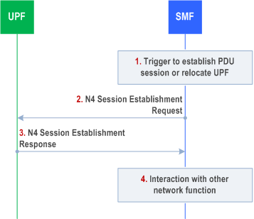
Step 1.
SMF receives the trigger to establish a new PDU Session or change the UPF for an established PDU Session.
Step 2.
The SMF sends an N4 session establishment request message to the UPF that contains the structured control information which defines how the UPF needs to behave. If the SMF is a V-SMF and it supports HR-SBO for the PDU session, V-SMF includes SUPI, HPLMN DNN and S-NSSAI, and an indication that the UE PDU session is working in HR-SBO mode.
If the UPF supports Nupf_EventExposure service, the SMF should include DNN and S-NSSAI in the N4 Session Establishment procedure.
Step 3.
The UPF responds with an N4 session establishment response message containing any information that the UPF has to provide to the SMF in response to the control information received.
If the UPF (by configuration or other means) utilizes an NWDAF, UPF adds the NWDAF serving the UE identified by the NWDAF instance ID. Per NWDAF service instance the Analytics ID(s) are also included.
Step 4.
The SMF interacts with the network function which triggered this procedure (e.g. AMF or PCF).
4.4.1.3 N4 Session Modification procedure p. 217
The N4 Session Modification procedure is used to update the N4 session context of an existing PDU Session at the UPF, which is executed between SMF and UPF whenever PDU Session related parameters have to be modified.
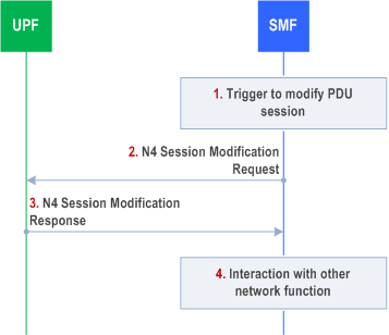
Step 1.
SMF receives the trigger to modify the existing PDU Session.
Step 2.
The SMF sends an N4 session modification request message to the UPF that contains the update for the structured control information which defines how the UPF needs to behave.
Step 3.
The UPF identifies the N4 session context to be modified by the N4 Session ID. Then, the UPF updates the parameters of this N4 session context according to the list of parameters sent by the SMF. The UPF responds with an N4 session modification response message containing any information that the UPF has to provide to the SMF in response to the control information received.
Step 4.
The SMF interacts with the network entity which triggered this procedure (e.g. AMF or PCF).
4.4.1.4 N4 Session Release procedure p. 217
The N4 session release procedure is used to remove the N4 session context of an existing PDU Session at the UPF.
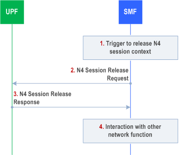
Step 1.
SMF receives the trigger to remove the N4 session context for the PDU Session.
Step 2.
The SMF sends an N4 session release request message to the UPF.
Step 3.
The UPF identifies the N4 session context to be removed by the N4 Session ID and removes the whole session context. The UPF responds with an N4 session release response message containing any information that the UPF has to provide to the SMF.
Step 4.
The SMF interacts with the network entity which triggered this procedure (e.g. AMF or PCF).
4.4.2 N4 Reporting Procedures p. 218
4.4.2.1 General p. 218
The N4 reporting procedure is used by the UPF to report events to the SMF.
4.4.2.2 N4 Session Level Reporting Procedure p. 218
This procedure is used by the UPF to report events related to an N4 session for an individual PDU Session. The triggers for event reporting were configured on the UPF during N4 Session Establishment/Modification procedures by the SMF.
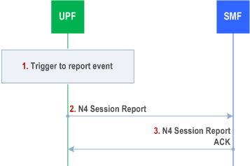
Step 1.
The UPF detects that an event has to be reported. The reporting triggers include the following cases:
Step 2.
- Measurement information reporting (Usage Report). Measurement information shall be collected in the UPF and reported to the SMF as defined in clause 5.8 and clause 5.12 of TS 23.501.
- Start of traffic detection (Usage Report). When traffic detection is requested by SMF and the start of traffic is detected for a Packet Detection Rule (PDR) as described in clause 5.8 of TS 23.501, the UPF shall report the start of traffic detection to the SMF and indicate the corresponding PDR rule ID.
- Stop of traffic detection (Usage Report). When traffic detection is requested by SMF and the end of traffic is detected for a PDR as described in clause 5.8 of TS 23.501, the UPF shall report the stop of traffic detection to the SMF and indicate the corresponding PDR rule ID.
- Detection of 1st downlink packet for a QoS Flow of a PDU Session with UP Connection deactivated (Downlink Data Report). When UPF receives the first downlink packet for a QoS Flow but no N3/N9 tunnel for downlink data transmission exists and the buffering is performed by the UPF, it shall report the detection of 1st downlink packet to SMF also indicating the QoS Flow for which the downlink packet was received (for the purpose of downlink data notification). The UPF shall also report the DSCP of the packet if the PDU Session type is IP (to support the Paging Policy Differentiation feature described in clause 5.4.3 of TS 23.501).
- Detection of PDU Session Inactivity for a specified period (User Plane Inactivity Report). When an Inactivity Timer for a PDU Session is provided by SMF during N4 Session Establishment/Modification procedure and the UPF detects the PDU Session has no data transfer for a period specified by the Inactivity Timer, it shall report PDU Session Inactivity to the SMF.
- QoS Monitoring Report (Session Report). When the QoS Monitoring is enabled for the QoS Flow, performs the necessary actions as described in clauses 5.8.2.18 and 5.45 of TS 23.501. The details about when and how the UPF sends the QoS Monitoring reports are described in clause 5.8.2.18 of TS 23.501. When receiving the QoS monitoring reports from the UPF, the SMF sends the reports to the target NF according to the information for QoS Monitoring received in the PCC rules as described in TS 23.503.
- TSC Management Information available (TSC Management Information). When TSC management information is available, the UPF shall provide the TSC management information in the TSC Management Information to the SMF as defined in clause 5.8.5.14 of TS 23.501.
- Discard Downlink Traffic detection (Downlink Data Report). When discarded downlink traffic detection is requested by SMF for a PDR and the first downlink packet is discarded after being buffered for this PDR as described in clause 5.8.2.19.2 of TS 23.501, the UPF shall report the discarded downlink traffic detection to the SMF and indicate the corresponding PDR rule ID (for the purpose of downlink data delivery status notification).
- Buffered Downlink Traffic detection (Downlink Data Report). When buffered downlink traffic detection is requested by SMF for a PDR and the first downlink packet is buffered for this PDR as described in clause 5.8.2.19.2 of TS 23.501, the UPF shall report the buffered downlink traffic detection to the SMF and indicate the corresponding PDR rule ID (for the purpose of downlink data delivery status notification).
- N6 Traffic Parameter Measurement Report (Session Report). When the N6 Traffic Parameters measurement report is requested by SMF for a QoS Flow as described in clause 5.37.8.2 of TS 23.501, the UPF shall report to the SMF the N6 Traffic Parameter(s) for the specified QoS Flow (i.e. the N6 jitter range associated with the DL periodicity and conditionally, the UL/DL periodicity).
The UPF sends an N4 session report message (N4 Session ID, list of [Usage Report, Downlink Data Report, Session Report, User Plane Inactivity Report, TSC Management Information]) to the SMF.
Step 3.
The SMF identifies the N4 session context based on the received N4 Session ID and applies the reported information for the corresponding PDU Session. The SMF responds with an N4 session report ACK message.
4.4.3 N4 Node Level Procedures p. 219
4.4.3.1 N4 Association Setup Procedure p. 219
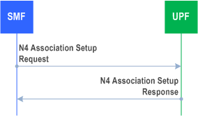
The N4 Association Setup procedure is used to setup an N4 association between the SMF and the UPF, to enable the SMF to use the resources of the UPF subsequently to establish N4 Sessions. The SMF and UPF may exchange the supported functionalities on each side during these procedures.
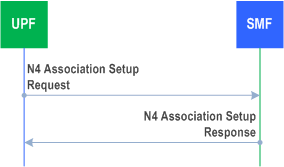
The setup of an N4 association is initiated by the SMF. SMF and UPF may additionally support an N4 association initiated by UPF.
The SMF should only establish an N4 association with a UPF that supports F-TEID allocation at the UPF.
The SMF initiates the N4 Association Setup procedure to request to setup an N4 association towards a UPF prior to establishing a first N4 session on this UPF.
When receiving an N4 Association Setup Request, the UPF shall send an N4 Association Setup Response.
N4 Association Setup procedure can be used to request the UPF to measure and report the clock drift between the external time and 5GS time for one or more external time domains by provisioning External Clock Drift Report and providing the corresponding Time Domain number(s) as specified in TS 29.244. The SMF may omit the Time domain number in the request; in this case the UPF shall report the clock drift for all Time domains the UPF is connected to.
N4 Association Setup procedure may be used to request the UPF to measure the N6 delay for the connection between the UPF and the endpoint in the DN (e.g. EAS) as described in clause 5.8.2.23 of TS 23.501.
The UPF may initiate the N4 Association Setup procedure to request to setup an N4 association towards a SMF prior to establishing a first N4 session on this UPF.
When receiving an N4 Association Setup Request, the SMF shall send an N4 Association Setup Response.
4.4.3.2 N4 Association Update Procedure p. 220
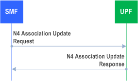
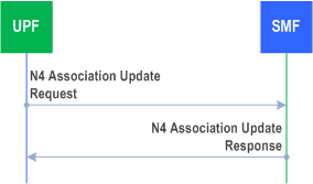
The N4 Association Update procedure shall be used to modify an existing N4 association between the SMF and the UPF. It may be initiated by the UPF or by the SMF to update the supported features or available resources of the UP function.
N4 Association Update procedure can be used by the SMF to update the provisioning of External Clock Drift Report as specified in clause 4.4.3.1.
N4 Association Update procedure may be used by the SMF to provide or update the provisioning of measurement assistance information of N6 delay for the connection between the UPF and the endpoint in the DN (e.g. EAS) as specified in clause 5.8.2.23 of TS 23.501.
4.4.3.3 N4 Association Release Procedure p. 221
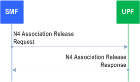
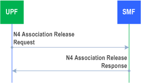
The N4 Association Release procedure shall be used to terminate the N4 association between the SMF and the UPF due to e.g. OAM reasons. The N4 Association Release Request may be initiated by the SMF or UPF.
4.4.3.4 N4 Report Procedure p. 221
The N4 Report procedure shall be used by the UPF to report information to the SMF which is not related to a specific N4 session, e.g. to report a user plane path failure affecting all the N4 sessions towards a remote GTP-U peer.
N4 Report procedure can be used by the UPF to report the clock drift between the external time and 5GS time for one or more external working domains as specified in TS 29.244.
N4 Report procedure may be used by the UPF to report the N6 delay measurements for the connection between the UPF and the endpoint in the DN as described in clause 5.8.2.23 of TS 23.501.
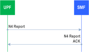
The UPF detects that an event has to be reported and starts the procedure by sending an N4 Report message (UPF ID, list of [event, status]) to the SMF. The SMF responds with an N4 report ACK message (SMF ID). The event parameter contains the name of the event and UPF ID. The status parameter contains the actual information the control plane function is interested in. If the UPF detects clock drifting between 5G time and one or more time working domains, the UPF reports the corresponding external domain number and the time offset and cumulative rate Ratio according to the provisioning from the SMF as defined in clause 5.27.2 of TS 23.501. If the UPF detects that the configured reporting periodicity or reporting threshold is reached on N6 delay measurements, the UPF reports the corresponding N6 delay measurement information as defined in clause 5.8.2.23 of TS 23.501. The UPF includes the Network Instance (if available) and the combination of DNN and S-NSSAI (if available) in the report.
4.4.3.5 N4 PFD management Procedure p. 222
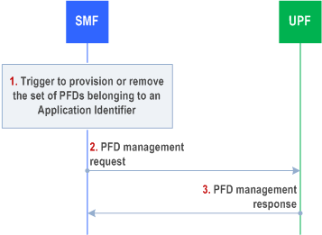
This N4 procedure is used by the SMF to provision or remove all PFD(s) belonging to an Application Identifier in the UPF. PFD sets belonging to different Application Identifiers can be managed with the same PFD management request message.
The N4 PFD management procedure is a node level procedure, i.e. independent of any PDU Session.
Step 1.
The SMF is triggered to provision or remove the PFD set belonging to an Application Identifier in the following cases:
When the caching timer expires and there's no active PCC rule that refers to the corresponding application identifier, the SMF informs the UPF to remove the PFD(s) identified by the Application Identifier.
When a PCC rule is provided for an Application Identifier corresponding to the PFD(s) that are not already provided to the UPF, the SMF shall provide the PFD(s) to the UPF (if there are no PFD(s) cached, the SMF retrieves them from the NEF (PFDF), as described in TS 23.503).
When any update of the PFD(s) is received from NEF (PFDF) and there are still active PCC rules in UPF for the Application Identifier.
Step 2.
The SMF sends a PFD management request to the UPF to provision/remove the PFD(s) corresponding to the Application Identifier(s).
Step 3.
The UPF updates the PFD(s) according to the request and acknowledges by responding with a PFD management response message.
4.4.4 SMF Pause of Charging procedure p. 223
The SMF Pause of Charging procedure aims for the SMF charging and usage monitoring data to more accurately reflect the downlink traffic actually sent to the AN.
The following are example triggers for the SMF to enable the pause of charging
PDUSession_Create Response during the PDU Session Establishment procedure. This is an indication to the V-SMF that when the criteria for pause of SMF charging are met at the VPLMN (as described further down in this clause) charging at the H-SMF can be paused.
The H-SMF shall stop any charging and usage monitoring actions for the PDU Session upon receiving a "Start Pause of Charging" Indication in a Nsmf_PDUSession_Update request from the V-SMF. When the H-SMF receives a Nsmf_PDUSession_Update request for a PDU Session with a "Stop Pause of Charging" Indication, then the H-SMF shall resume charging for the PDU Session.
Regardless of operator policy/configuration, the downlink user plane packets received at the (V-)UPF shall trigger Data Notifications as described in clause 4.2.3.3.
When the (V-)SMF receives a Nsmf_PDUSession_UpdateSMContext request or a Namf_EventExposure_Notify about UE reachability, the (V-)SMF shall consider the PDU Session charging as being unpaused if it had been paused previously.
- Operator specified criteria/threshold (e.g. number/fraction of packets/bytes dropped at UPF in downlink since last time the N3 tunnel towards the AN was released). The SMF requests the UPF to notify the SMF whenever the criteria/threshold is met.
- Indication of "Radio Link Failure" (see clause 4.2.6).
- Towards the UPF(s) where the Usage Reporting is configured, the SMF shall modify the Usage Reporting Rules for the PDU Session so that the usage collection for charging is stopped.
- The SMF may request the UPF to limit the rate of downlink traffic sent to the downstream UPF or the AN.
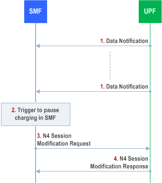
Step 1.
The UPF receives downlink data packets for a PDU Session that does not have an N3 tunnel and the UPF sends data notification to the SMF. The packets are buffered or discarded in the UPF based on operator policy.
Step 2.
Based on operator policy/configuration the SMF triggers the procedure to pause PDU Session charging. Triggering criteria are based on SMF operator policy/configuration.
Step 3.
SMF sends a N4 Session Modification Request message to the UPF where the Usage Reporting is configured, modifying the Usage Reporting Rules for the PDU Session so that the usage collection for charging is stopped. In home routed roaming scenarios, the V-SMF sends a Nsmf_PDUSession_Update request to the H-SMF with a "Start Pause of Charging" Indication. The H-SMF then requests the H-UPF to stop usage collection as mentioned before.
Step 4.
UPF confirms with a N4 Session Modification Response message.