Content for TS 23.502 Word version: 19.2.0
1…
4.2.2.2.2
4.2.2.2.3…
4.2.2.3…
4.2.3…
4.2.3.3
4.2.4…
4.2.6
4.2.7…
4.2.9…
4.2.11…
4.2.11.5…
4.3…
4.3.2.2.2
4.3.2.2.3…
4.3.3…
4.3.3.3
4.3.4…
4.3.4.3
4.3.5…
4.3.5.2…
4.3.5.4…
4.3.5.6…
4.3.6…
4.4…
4.5…
4.9…
4.9.1.3…
4.9.2…
4.11…
4.11.1…
4.11.1.2.2
4.11.1.2.3
4.11.1.3…
4.11.1.3.3…
4.11.1.4…
4.11.1.5…
4.11.2…
4.11.3…
4.12…
4.12.6…
4.12a…
4.12b…
4.13…
4.13.4…
4.13.6…
4.14…
4.15…
4.15.3.2.5…
4.15.4…
4.15.6…
4.15.6.7…
4.15.6.13…
4.15.6.14…
4.15.9…
4.15.9.4…
4.15.13…
4.15.13.4…
4.16…
4.16.4…
4.16.8…
4.16.11…
4.16.14…
4.16.15…
4.17…
4.17.9…
4.18…
4.19…
4.22…
4.23…
4.23.7…
4.23.7.3.3
4.23.7.3.4…
4.23.9…
4.23.9.4…
4.23.11…
4.24…
4.25…
4.25.6…
4.26…
5…
5.2.3…
5.2.5…
5.2.6…
5.2.7…
5.2.8…
5.2.9…
5.2.12…
5.2.18…
A…
E…
F…
G
H…
4.2.3 Service Request procedures p. 64
4.2.3.1 General p. 64
The Service Request procedure is used by a UE in CM-IDLE state or the 5GC to request the establishment of a secure connection to an AMF. The Service Request procedure is also used both when the UE is in CM-IDLE and in CM-CONNECTED to activate a User Plane connection for an established PDU Session. The Service Request procedure is also used to release the connection to an AMF.
For Home routed PDU sessions, by replacing the I-SMF with V-SMF and SMF with H-SMF the same procedure as defined in clause 4.23.4 is reused.
The UE shall not initiate a Service Request procedure if there is an ongoing Service Request procedure.
4.2.3.2 UE Triggered Service Request p. 65
The UE in CM-IDLE state initiates the Service Request procedure in order to send uplink signalling messages, user data, to request emergency services fallback, or as a response to a network paging request. The UE shall not initiate UE Triggered Service Request from CM-IDLE if there is a Service Gap timer running. After receiving the Service Request message, the AMF may perform authentication. After the establishment of the signalling connection to an AMF, the UE or network may send signalling messages, e.g. PDU Session establishment from UE to the SMF, via the AMF.
The Service Request procedure is used by a UE in CM-CONNECTED to request activation of a User Plane connection for PDU Sessions and to respond to a NAS Notification message from the AMF. When a User Plane connection for a PDU Session is activated, the AS layer in the UE indicates it to the NAS layer.
The Service Request procedure is used by the Multi-USIM UE over 3GPP access, in:
- CM-CONNECTED state to request release of the UE connection, stop data transmission, discard of any pending data and optionally, store Paging Restriction Information; or
- CM-IDLE state to request removal of Paging Restriction Information. The Multi-USIM UE shall not execute UE triggered Service Request procedure with Release Request indication if regulatory prioritized services (e.g. emergency service, emergency callback waiting) are ongoing. After an emergency call, the UE shall not execute a UE triggered Service Request procedure with Release Request indication for a duration which is sufficient for emergency call back.
- CM-IDLE state to respond to paging with a Reject Paging Indication that indicates that N1 connection shall be released and no user plane connection shall be established. The UE optionally provides the Paging Restriction Information. The UE may be unable to respond to paging with a Reject Paging Indication, e.g. due to UE implementation constraints.
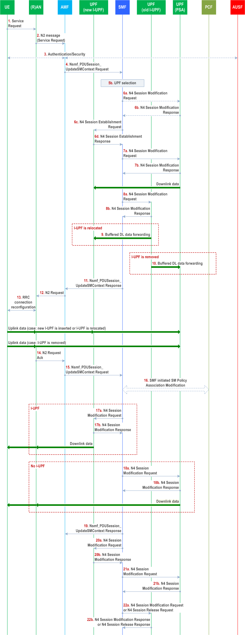
Step 1.

Step 2.
Step 3a.
Step 3.
Step 4.
Step 5a.
Step 5b.
Step 6a.
Step 6b.
Step 6c.
Step 6d.
Step 7a.
Step 7b.
Step 8a.
Step 8b.
Step 9.
Step 10.
Step 11.
Step 12.
Step 13.
Step 14.
Step 15.
Step 16.
Step 17a.
Step 17b.
Step 18a.
Step 18b.
Step 19.
Step 20a.
Step 20b.
Step 21a.
Step 21b.
Step 22a.
Step 22b.
For the mobility related events described in clause 4.15.4, the AMF invokes the Namf_
UE to (R)AN:
AN message (
The NAS message container shall be included if the UE is sending a Service Request message as an Initial NAS message and the UE needs to send non-cleartext IEs, see clause 4.4.6 of TS 24.501.
The Multi-USIM UE in CM-CONNECTED state may include the Release Request indication and optionally Paging Restriction Information in the Service Request message over 3GPP access, if the UE intends to leave CM-CONNECTED state.
The Multi-USIM UE in CM-IDLE state may include the Release Request indication and not include Paging Restriction Information in the Service Request message over 3GPP access, if the UE intends to delete the Paging Restriction Information.
If the Multi-USIM UE in CM-IDLE state decides not to accept the paging, it may send a Service Request message including a Reject Paging Indication and optionally Paging Restriction Information, unless it is not able to send this message e.g. due to UE implementation constraints.
The List Of PDU Sessions To Be Activated is provided by UE when the UE wants to re-activate the PDU Session(s). The List Of Allowed PDU Sessions is provided by the UE when the Service Request is a response of a Paging or a NAS Notification for a PDU Session associated with non-3GPP access and identifies the PDU Sessions that can be transferred to 3GPP access.
In the case of NG-RAN:
AN parameters,
Service Request (
).
Service Request (
List Of PDU Sessions To Be Activated,
List Of Allowed PDU Sessions,
security parameters,
PDU Session status,
5G-S-TMSI,
[NAS message container],
Exempt Indication,
[Release Request indication],
[Paging Restriction Information],
[Reject Paging Indication]
)
List Of Allowed PDU Sessions,
security parameters,
PDU Session status,
5G-S-TMSI,
[NAS message container],
Exempt Indication,
[Release Request indication],
[Paging Restriction Information],
[Reject Paging Indication]
- The AN parameters include 5G-S-TMSI, Selected PLMN ID (or PLMN ID and NID, see clause 5.30 of TS 23.501), Establishment cause and may also include NSSAI information. The Establishment cause provides the reason for requesting the establishment of an RRC connection. Whether and how the UE includes the NSSAI information as part of the AN parameters is dependent on the value of the Access Stratum Connection Establishment NSSAI Inclusion Mode parameter, as specified in clause 5.15.9 of TS 23.501.
- The UE sends Service Request message towards the AMF encapsulated in an RRC message to the NG-RAN. The RRC message(s) that can be used to carry the 5G-S-TMSI and this NAS message are described in TS 38.331 and TS 36.331.
Step 2.
(R)AN to AMF: N2 Message (N2 parameters, Service Request).
Details of this step are described in TS 38.413. If the AMF can't handle the Service Request it will reject it.
When NG-RAN is used, the N2 parameters include the 5G-S-TMSI, Selected PLMN ID (or PLMN ID and NID, see clause 5.30 of TS 23.501), Location information and Establishment cause, UE Context Request.
If the UE is in CM-IDLE state, the NG-RAN obtains the 5G-S-TMSI in RRC procedure. NG-RAN selects the AMF according to 5G-S-TMSI. The Location Information relates to the cell in which the UE is camping.
Based on the PDU Session status, the AMF may initiate PDU Session Release procedure in the network for the PDU Sessions whose PDU Session ID(s) were indicated by the UE as not available.
When the Establishment cause is associated with priority services (e.g. MPS, MCX), or when the AMF determines that the UE has priority subscription (e.g. MPS, MCX) in the UDM, the AMF includes a Message Priority header to indicate priority information. Other NFs relay the priority information by including the Message Priority header in service-based interfaces, as specified in TS 29.500.
The AMF enforces the Mobility Restrictions as specified in clause 5.3.4.1.1 of TS 23.501.
If there is a Service Gap timer running in AMF for the UE and the AMF is not waiting for a MT paging response from the UE and the Service Request is not for regulatory prioritized services like Emergency services or not for exception reporting, the AMF rejects the Service Request with an appropriate cause. In addition, AMF may also provide a UE with a Mobility Management Back-off timer set to the remaining value of the Service Gap timer.
If the AMF supports RACS and the AMF detects that the selected PLMN is different from the currently registered PLMN for the UE, the AMF determines the UE Radio Capability ID of the newly selected PLMN to the gNB as described in clause 5.4.4.1a of TS 23.501.
For NR satellite access, the AMF may decide to verify the UE location and determine whether the PLMN is allowed to operate at the UE location, as described in clause 5.4.11.4 of TS 23.501. If the UE receives a Service Reject message with cause value indicating that the PLMN is not allowed to operate in the present UE location, the UE shall attempt to select a PLMN, as specified in TS 23.122.
Step 3a.
AMF to (R)AN: N2 Request (security context, Mobility Restriction List, list of recommended cells / TAs / NG-RAN node identifiers).
If the 5G-AN had requested for UE Context or there is a requirement for AMF to provide this e.g. the AMF needs to initiate fallback procedure as in clause 4.13.4.2 for Emergency services, AMF initiates NGAP procedure as specified in TS 38.413. The AMF may provide the indication of NCR-MT authorization information in the UE Context. For UE in CM-IDLE state, 5G-AN stores the Security Context in the UE AN context. Mobility Restriction List is described in clause 5.3.4.1 of TS 23.501.
The 5G-AN uses the Security Context to protect the messages exchanged with the UE as described in TS 33.501.
If the NG-RAN node had provided the list of recommended cells / TAs / NG-RAN node identifiers during the AN Release procedure (see clause 4.2.6), the AMF shall include it in the N2 Request. The RAN may use this information to allocate the RAN Notification Area when the RAN decides to enable RRC_INACTIVE state for the UE.
Step 3.
If the Service Request was not sent integrity protected or integrity protection verification failed, the AMF shall reject the Service Request as stated in TS 24.501.
If the UE in CM-IDLE state triggered the Service Request to establish a signalling connection only, after successful establishment of the signalling connection the UE and the network can exchange NAS signalling and steps 4 to 11 and 15 to 22 are skipped.
If the UE in Non-Allowed Area triggered the Service Request with an indication that the message is exempted from restriction (e.g. Non-Allowed Area), the AMF should accept the Service Request. In this case, if the UE is in Non-Allowed Area, the AMF rejects user plane setup request from the SMF except for emergency services.
If the procedure was triggered in response to paging or NAS notification indicating non-3GPP access and the AMF received N1 SM Container only from the SMF in step 3a of clause 4.2.3.3, the AMF sends the NAS signalling including the N1 SM Container to the UE in step 7 of clause 4.2.3.3 without updating the access associated to the PDU Session.
If the Service Request message is received over 3GPP access without a Release Request indication or a Reject Paging Indication, the AMF shall delete any stored Paging Restriction Information for this UE and stop restricting paging accordingly.
If the Service Request message over 3GPP access includes a Release Request indication or a Reject Paging Indication, then:
- the AMF may accept or reject the received Paging Restriction Information requested by the UE based on operator policy. If the AMF rejects the Paging Restriction Information, the AMF removes any stored Paging Restriction Information from the UE context and discards the UE requested Paging Restriction Information. If the AMF accepts the Paging Restriction Information from the UE, the AMF stores the Paging Restriction Information from the UE in the UE context.
- If no Paging Restriction Information is provided, no paging restrictions apply and the AMF removes any stored Paging Restriction Information from the UE context.
- no User Plane resources are established and instead the AMF triggers the AN Release procedure as described in clause 4.2.6.
Step 4.
[Conditional] AMF to SMF:
PDUSession_UpdateSMContext Request is invoked:
PDUSession_UpdateSMContext Request to SMF(s) associated with the PDU Session(s) with Operation Type set to "UP activate" to indicate establishment of User Plane resources for the PDU Session(s). The AMF determines Access Type and RAT Type, see clause 4.2.2.2.1. If the RAT type is NB-IoT, the AMF shall ensure that the number of PDU session(s) for which UP connection(s) are active does not exceed this UE's maximum number of supported user plane resources (0, 1 or 2) based on whether the UE supports UP data transfer and the UE 5GMM Core Network Capability as described in clause 5.31.19 of TS 23.501.
If the procedure was triggered in response to paging or NAS Notification indicating non-3GPP access, the AMF received N2 SM Information in step 3a of clause 4.2.3.3 and the PDU Session for which the UE was paged or notified is not in the List Of Allowed PDU Sessions provided by the UE, the AMF notifies the SMF that the UE is not reachable. For other PDU Sessions in the List Of Allowed PDU Sessions the Service Request Procedure succeeds without re-activating the User Plane of any PDU Sessions, unless they have also been included by the UE in the List Of PDU Sessions To Be Activated.
If the procedure was triggered in response to paging or NAS notification indicating non-3GPP access and the PDU Session for which the UE was paged or notified is in the List Of Allowed PDU Sessions provided by the UE and the AMF received N2 SM Information only or N1 SM Container and N2 SM Information from the SMF in step 3a of clause 4.2.3.3, the AMF notifies the SMF that the access type of the PDU session can be changed. The AMF discards any already received N1 SM Container and N2 SM Information. In Home Routed roaming case, the V-SMF triggers Nsmf_PDUSession_Update service operation towards the H-SMF to notify the access type of the PDU Session can be changed and the procedure continues as specified in clause 4.3.3.3 from step 1a to step 10.
If the UE is accessing via the NB-IoT RAT, the AMF may inform all (H-)SMFs whether the RRC establishment cause is set to "MO exception data", as described in clause 5.31.14.3 of TS 23.501. The AMF may immediately send the MO Exception Data Counter to the (H-)SMF.
If the AMF, based on configuration, as described in clauses 5.43.4 and 5.43.2 of TS 23.501, is aware that satellite backhaul category and/or GEO Satellite ID has changed and needs to be updated to the SMF, the AMF includes the new Satellite backhaul category or new GEO Satellite ID or both as described in clauses 5.43.4 and 5.43.2 of TS 23.501.
The AMF may receive a Service Request to establish another NAS signalling connection via a new NG-RAN while it has maintained an old NAS signalling connection for UE still via an old NG-RAN. The new NG-RAN and the old NG-RAN can be the same NG-RAN node. In this case, AMF shall trigger the AN release procedure toward the old NG-RAN to release the old NAS signalling connection as defined in clause 4.2.6 and:
Nsmf_PDUSession_UpdateSMContext Request (
The Nsmf_
PDU Session ID(s),
Operation Type,
UE location information,
Access Type,
RAT Type,
UE presence in LADN service area,
Indication of Access Type can be changed,
[MO Exception Data Counter],
[Satellite backhaul category],
[GEO Satellite ID]
).
Operation Type,
UE location information,
Access Type,
RAT Type,
UE presence in LADN service area,
Indication of Access Type can be changed,
[MO Exception Data Counter],
[Satellite backhaul category],
[GEO Satellite ID]
- If the UE identifies List Of PDU Sessions To Be Activated in the Service Request message;
- This procedure is triggered by the SMF but the PDU Session(s) identified by the UE correlates to other PDU Session ID(s) than the one triggering the procedure; or
- If this procedure is triggered by the SMF in response to paging or NAS notification indicating 3GPP access or if this step onwards is invoked following step 4a of clause 4.2.3.3 and the current UE location is outside the "Area of validity for the N2 SM information" provided by the SMF in step 3a of clause 4.2.3.3 or the "Area of validity for the N2 SM information" was not provided by the SMF in step 3a of clause 4.2.3.3, the AMF shall not send the N2 information provided by the SMF in step 3a of clause 4.2.3.3. Otherwise, if the current UE location is in the "Area of validity for the N2 SM information", steps 4 to 11 are skipped; or
- If this procedure is triggered by the SMF in response to paging or NAS notification indicating non-3GPP access and the AMF received N2 SM Information only, or both N1 SM Container and N2 SM Information in step 3a of clause 4.2.3.3.
- For the PDU Sessions indicated by the UE in the List Of PDU Sessions To Be Activated, the AMF requests the SMF to activate the PDU Session(s) immediately by performing this step 4; and
- For the PDU Sessions indicated by the old NG-RAN in the "List of PDU Session ID(s) with active N3 user plane" but not in the List Of PDU Sessions To Be Activated sent by the UE, the AMF requests the SMF to deactivate the PDU Session(s).
Step 5a.
Void
Step 5b.
If the PDU Session ID corresponds to a LADN and the SMF determines that the UE is outside the area of availability of the LADN based on the "UE presence in LADN service area" from the AMF, the SMF decides to (based on local policies) either:
- keep the PDU Session, but reject the activation of User Plane connection for the PDU Session and inform the AMF about it. If the procedure has been triggered by a Network Triggered Service Request as described in clause 4.3.2.3, the SMF may notify the UPF that originated the Data Notification to discard downlink data for the PDU Sessions and/or to not provide further Data Notification messages; or
- to release the PDU Session: the SMF releases the PDU Session and informs the AMF that the PDU Session is released.
- accepts the activation of UP connection and continue using the current UPF(s);
- accepts the activation of UP connection and selects a new intermediate UPF (or add/remove an intermediate UPF), if the UE has moved out of the service area of the UPF that was previously connecting to the AN, while maintaining the UPF(s) acting as PDU Session Anchor. The steps to perform I-UPF addition/change/removal are described as conditional steps in the following of the current procedure; or
- rejects the activation of UP connection of a PDU Session of SSC mode 2 and trigger re-establishment of the PDU Session after Service Request procedure to perform the allocation of a new UPF to act as PDU Session Anchor, e.g. the UE has moved out of the service area of the anchor UPF which is connecting to NG-RAN.
-
trigger re-establishment of PDU Session. After Service Request procedure, SMF sends N1 SM message to the UE via the AMF by invoking Namf_
Communication_ containing the cause indicating PDU Session re-establishment is required for the UE; orN1N2MessageTransfer - keep the PDU Session, but reject the activation request of User Plane connection for the PDU Session and inform the AMF about it; or
- release the PDU Session after Service Request procedure.
Step 6a.
[Conditional] SMF to UPF (PSA): N4 Session Modification Request.
Depending on the network deployment, the CN Tunnel Info of UPF (PSA) allocated for N3 or N9 interface may be changed during the Service Request procedure, e.g. UPF connected to different IP domains. If different CN Tunnel Info need be used, the SMF sends N4 Session Modification Request message to UPF (PSA) and requests CN Tunnel Info providing the target Network Instance.
Step 6b.
[Conditional] UPF (PSA) to SMF: N4 Session Modification Response.
The UPF (PSA) sends an N4 Session Establishment Response message to the SMF. The UPF provides CN Tunnel Info to the SMF. The UPF (PSA) associate the CN Tunnel Info with UL Packet detection rules provided by the SMF.
If the redundant I-UPFs are used for URLLC, each I-UPF provides UL CN Tunnel Info for N3 interface to the SMF in the N4 Session Establishment Response message.
If the redundant N3 tunnels are used for URLLC, the UPF (PSA) provides redundant UL CN Tunnel Info for N3 interface to the SMF in N4 Session Establishment Response message.
Step 6c.
[Conditional] SMF to new UPF (intermediate): N4 Session Establishment Request.
If the SMF selects a new UPF to act as intermediate UPF for the PDU Session, or if the SMF selects to insert an intermediate UPF for a PDU Session which did not have an intermediate UPF, an N4 Session Establishment Request message is sent to the new UPF, providing Packet detection, Data forwarding, enforcement and reporting rules to be installed on the intermediate UPF. The CN Tunnel Info (on N9) of PSA, i.e. which is used to establish the N9 tunnel, for this PDU Session is also provided to the intermediate UPF.
If a new UPF is selected by the SMF to replace the old (intermediate) UPF, the SMF may also include a request for the new UPF to allocate a second tunnel endpoint for buffered DL data from the old I-UPF and to indicate via usage reporting end marker reception on this second tunnel. In this case, the UPF is instructed by the SMF to buffer the DL data it may receive at the same time from the UPF (PSA).
Step 6d.
New UPF (intermediate) to SMF: N4 Session Establishment Response.
The new intermediate UPF sends an N4 Session Establishment Response message to the SMF. The UPF provides DL CN Tunnel Info as requested by SMF in step 6c. The SMF starts a timer, to be used in step 22a to release the resource in old intermediate UPF if there is one.
Step 7a.
[Conditional] SMF to UPF (PSA): N4 Session Modification Request.
If the SMF selects a new UPF to act as intermediate UPF for the PDU Session, the SMF sends N4 Session Modification Request message to PDU Session Anchor UPF, providing DL Tunnel Info from new intermediate UPF. If the new intermediate UPF was added for the PDU Session, the UPF (PSA) begins to send the DL data to the new I-UPF as indicated in the DL CN Tunnel Info. The UPF (PSA) sends one or more "end marker" packets for each N9 tunnel to the old I-UPF immediately after switching the path to new I-UPF.
If the Service Request is triggered by the network and the SMF removes the old I-UPF but does not replace it with a new I-UPF, the SMF may also include a request for the UPF to allocate a second tunnel endpoint for buffered DL data from the old I-UPF and to indicate end marker reception on this second tunnel via usage reporting. In this case, the UPF (PSA) begins to buffer the DL data it may receive at the same time from the N6 interface. The UPF (PSA) sends one or more "end marker" packets for each N9 tunnel to the old I-UPF immediately after switching the path to (R)AN.
Step 7b.
The UPF (PSA) sends N4 Session Modification Response message to SMF.
If requested by SMF, the UPF (PSA) sends DL CN tunnel info for the old (intermediate) UPF to the SMF. The SMF starts a timer, to be used in step 22a to release the resource in old intermediate UPF if there is one.
If the UPF that connects to RAN is the UPF (PSA) and if the SMF finds that the PDU Session is activated when receiving the Nsmf_PDUSession_UpdateSMContext Request in step 4 with Operation Type set to "UP activate" to indicate establishment of User Plane resources for the PDU Session(s), it deletes the AN Tunnel Info and initiates an N4 Session Modification procedure to remove Tunnel Info of AN in the UPF.
Step 8a.
[Conditional] SMF to old UPF (intermediate):
PDUSession_UpdateSMContext Request in step 4 with Operation Type set to "UP activate" to indicate establishment of User Plane resources for the PDU Session(s), it deletes the AN Tunnel Info and initiates an N4 Session Modification procedure to remove Tunnel Info of AN in the UPF.
N4 Session Modification Request (
New UPF address,
New UPF DL Tunnel ID )
If the service request is triggered by the network and the SMF removes the old (intermediate) UPF, the SMF sends the N4 Session Modification Request message to the old (intermediate) UPF, providing the DL Tunnel Info for the buffered DL data. If the SMF allocated new I-UPF, the DL Tunnel Info is from the new (intermediate) UPF acting as N3 terminating point. If the SMF did not allocate a new I-UPF, the DL Tunnel Info is from the new UPF (PSA) acting as N3 terminating point. The SMF starts a timer to monitor the forwarding tunnel as step 6d or 7b.
If the old I-UPF receives end marker packets and there is no associated tunnel to forward these packets, the old I-UPF discards the received end marker packets and does not send any Data Notification to SMF.
If the SMF find the PDU Session is activated when receiving the Nsmf_New UPF DL Tunnel ID )
Step 8b.
old UPF (intermediate) to SMF: N4 Session Modification Response
The old (intermediate) UPF sends N4 Session Modification Response message to SMF.
Step 9.
[Conditional] old UPF (intermediate) to new UPF (intermediate): buffered downlink data forwarding
If the I-UPF is changed and forwarding tunnel was established to the new I-UPF, the old (intermediate) UPF forwards its buffered data to the new (intermediate) UPF acting as N3 terminating point. If indicated by SMF in step 6c, the new I-UPF reports to SMF when end marker packet is received. Then the SMF initiates N4 Session Modification procedure to indicate the new I-UPF to send the buffered downlink packet(s) received from the UPF (PSA).
Step 10.
[Conditional] old UPF (intermediate) to UPF (PSA): buffered downlink data forwarding
If the old I-UPF is removed and no new I-UPF is assigned for the PDU Session and forwarding tunnel was established to the UPF (PSA), the old (intermediate) UPF forwards its buffered data to the UPF (PSA) acting as N3 Terminating Point. If indicated by SMF in step 7a, the UPF (PSA) reports to SMF when the end marker packet has been received. Then the SMF initiates N4 Session Modification procedure to request the UPF (PSA) to send the buffered DL data received from the N6 interface.
Step 11.
[Conditional] SMF to AMF:
PDUSession_UpdateSMContext Response to the AMF to establish the User Plane(s). The N2 SM information contains information that the AMF shall provide to the NG-RAN. The SMF may indicate for each QoS Flow whether redundant transmission shall be performed by a corresponding redundant transmission indicator. If the SMF decided to change the PSA UPF for the SSC mode 3 PDU Session, the SMF triggers the change of SSC mode 3 PDU Session anchor as an independent procedure described in clause 4.3.5.2 or clause 4.3.5.3 after accepting the activation of UP of the PDU Session.
For each QoS Flow, the SMF may at most request one of the following to the NG-RAN:
PDUSession_UpdateSMContext Response. Following are some of the cases:
Nsmf_PDUSession_UpdateSMContext Response (
If the UPF that connects to RAN is the UPF (PSA), the N3 CN Tunnel Info is the UL CN Tunnel Info of the UPF (PSA). If the UPF that connects to RAN is the new intermediate UPF, the CN N3 Tunnel Info is the UL Tunnel Info of the intermediate UPF.
For the PDU Session with redundant I-UPFs or with redundant N3 tunnels for URLLC, the two UL N3 CN Tunnel Info are included, the SMF also indicates the NG-RAN that one of the CN Tunnel Info is used as the redundancy tunnel of the PDU session as described in clause 5.33.2.2 of TS 23.501.
The SMF shall send N1 SM Container and/or N2 SM Information to the AMF when applicable. (e.g. when the SMF was notified from the AMF that the access type of the PDU Session can be changed in step 4).
For a PDU Session that the SMF has determined to accept the activation of UP connection in step 5a or 5b, the SMF generates only N2 SM information and sends Nsmf_
N2 SM information (
N1 SM Container,
Cause
).
PDU Session ID,
QFI(s),
QoS profile(s),
CN N3 Tunnel Info,
S-NSSAI,
User Plane Security Enforcement,
UE Integrity Protection Maximum Data Rate,
RSN,
PDU Session Pair ID
),
QFI(s),
QoS profile(s),
CN N3 Tunnel Info,
S-NSSAI,
User Plane Security Enforcement,
UE Integrity Protection Maximum Data Rate,
RSN,
PDU Session Pair ID
N1 SM Container,
Cause
- ECN marking for L4S at NG-RAN in the case of ECN marking for L4S in RAN as described in clause 5.37.3 of TS 23.501; or,
- Congestion information monitoring as described in clauses 5.45.3 and 5.37.4 of TS 23.501; or,
- provide information for ECN marking for L4S at UPF in the case of ECN marking for L4S by PSA UPF as described in clause 5.37.3 of TS 23.501.
- For each QoS Flow, the SMF may request the following to the N3IWF or TNGF:
- ECN marking for L4S at N3IWF or TNGF in the case of ECN marking for L4S in non-3GPP access as described in clause 5.37.3 of TS 23.501.
- If the PDU Session corresponds to a LADN and the UE is outside the area of availability of the LADN as described in step 5b;
- If the AMF notified the SMF that the UE is reachable only for regulatory prioritized service and the PDU Session to be activated is not for a regulatory prioritized service; or
-
If the SMF decided to change the PSA UPF for the requested PDU Session as described in step 5b. In this case, after sending Nsmf_
PDUSession_ Response, the SMF triggers another procedure to instruct UE to re-establish the PDU Session as described in clause 4.3.5.1 for SSC mode 2.UpdateSMContext - If the SMF received negative response in Step 6b due to UPF resource unavailability.
Step 12.
AMF to (R)AN:
PDUSession_UpdateSMContext Response service operations from all the SMFs associated with the UE are received.
If the NG-RAN node had provided the list of recommended cells / TAs / NG-RAN node identifiers during the AN Release procedure (see clause 4.2.6), the AMF shall include it in the N2 Request. The NG-RAN may use this information to allocate the RAN Notification Area when the NG-RAN decides to enable RRC_INACTIVE state for the UE.
The AMF includes the UE's "RRC Inactive Assistance Information" as defined in clause 5.3.3.2.5 of TS 23.501.
If the NG-RAN node does not support RACS and the AMF have UE Radio Capability ID but not the UE Radio Capability information, then AMF will use Nucmf_UECapabilityManagement_Resolve to try to retrieve the corresponding UE Radio Capability information.
If the NG-RAN node does not support RACS, or the AMF does not have UE Radio Capability ID in UE context, the AMF shall include the UE Radio Capability information, if available, to the NG-RAN node as described in TS 23.501. If the RAT Type is NB-IoT then NB-IoT specific UE Radio Access Capability Information is included instead, if available.
If AMF has UE Radio Capability ID in UE context valid for the PLMN the UE is currently in and the NG-RAN supports RACS, the AMF signals the UE Radio Capability ID. If the NG-RAN node does not have mapping between the UE Radio Capability ID and the corresponding UE radio capabilities, it shall use the non-UE associated procedure described in TS 38.413 to retrieve the mapping from the AMF.
The AMF may include the Core Network Assistance Information which includes Core Network assisted RAN parameters tuning and Core Network assisted RAN paging information as defined in TS 23.501.
If the UE included support for restriction of use of Enhanced Coverage, the AMF sends Enhanced Coverage Restricted information to the (R)AN in the N2 message.
If the UE and the AMF have negotiated to enable MICO mode and the AMF uses the Extended connected timer, then the AMF provides the Extended Connected time value to NG-RAN (see clause 5.31.7.3 of TS 23.501) in this step. The Extended Connected Time value indicates the minimum time the RAN should keep the UE in RRC_CONNECTED state regardless of inactivity.
If the AMF accepted MICO mode in the last registration procedure and knows there may be mobile terminated data or signalling pending, the AMF maintains the N2 connection for at least the Extended Connected Time as described in clause 5.31.7.3 of TS 23.501 and provides the Extended Connected Time value to the RAN in N2 message with Service Accept message. The RAN should keep the UE in RRC_CONNECTED state for an Extended Connected Time period in order to ensure the downlink data and/or signalling is delivered to the UE.
If the RAN receives two CN Tunnel Info for a PDU session in step 11 for redundant transmission, RAN also allocates two AN Tunnel Info correspondingly and indicate to SMF one of the AN Tunnel Info is used as the redundancy tunnel of the PDU session as described in clause 5.33.2.2 of TS 23.501.
N2 Request (
The Allowed NSSAI for the Access Type for the UE and if available, Partially Allowed NSSAI (as described in clause 5.15.17 of TS 23.501), are included in the N2 message. If the subscription information includes Tracing Requirements, the AMF includes Tracing Requirements in the N2 Request. If the subscription information includes QMC Configuration information, the AMF includes QMC Configuration information in the N2 Request.
If the UE triggered the Service Request while in CM-CONNECTED state, only N2 SM information received from SMF and MM NAS Service Accept are included in the N2 Request.
If the Service Request procedure is triggered by the Network (as described in clause 4.2.3.3) while the UE is in CM-CONNECTED state, only N2 SM information received from SMF is included in the N2 Request.
If the Service Request procedure is triggered by the Network (as described in clause 4.2.3.3) while the UE is in CM-IDLE state, only N2 SM information received from SMF and MM NAS Service Accept is included in the N2 Request.
For a UE that was in CM-IDLE state when the Service Request was triggered, the NG-RAN stores the Security Context. If the Service Request is not triggered by UE for a signalling connection only, RAN also stores QoS Information for the QoS Flows of the PDU Sessions that are activated and N3 Tunnel IDs in the UE RAN context and Mobility Restriction List (as described in clause 5.3.4.1 of TS 23.501).
MM NAS Service Accept includes PDU Session status in AMF. Any local PDU Session Release during the Session Request procedure is indicated to the UE via the Session Status. PDU Session Reactivation Result is provided in Service Accept for the PDU sessions in the List Of PDU Sessions To Be Activated and the PDU Session in the List of Allowed PDU Sessions which has caused paging or NAS notification. If the PDU Session Reactivation Result of a PDU Session is failure, the cause of the failure is also provided. One of the possible causes of failure for a PDU Session reactivation is when the AMF determines that the UE is not inside the NS-AoS of the network slice of the PDU Session.
If the AMF accepts the Paging Restriction Information sent from the UE, the AMF informs the UE about the acceptance/rejection of the requested Paging Restriction Information in the MM NAS Service Accept message.
If AMF receives multiple TAIs from the NG-RAN in step 2 and determines that some, but not all of them are forbidden by subscription or by operator policy, the AMF shall include the forbidden TAI(s) in the MM NAS Service Accept message.
If there are multiple PDU Sessions that involves multiple SMFs, AMF does not need to wait for responses from all SMFs in step 11 before it sends N2 SM information to the RAN. However, the AMF shall wait for all responses from the SMFs before it sends MM NAS Service Accept message to the UE.
AMF shall include at least one N2 SM information from SMF if this step is triggered for PDU Session User Plane activation. AMF may send additional N2 SM information from SMFs in separate N2 message(s) (e.g. N2 tunnel setup request), if there is any. Alternatively, if multiple SMFs are involved, the AMF may send one N2 Request message to (R)AN after all the Nsmf_
N2 SM information received from SMF,
security context,
Mobility Restriction List,
UE-AMBR,
List of UE-Slice-MBR(s) (optional and for 3GPP access type only),
MM NAS Service Accept,
list of recommended cells / TAs / NG-RAN node identifiers,
UE Radio Capability,
Core Network Assistance Information,
Tracing Requirements,
UE Radio Capability ID,
QMC Configuration information
).
security context,
Mobility Restriction List,
UE-AMBR,
List of UE-Slice-MBR(s) (optional and for 3GPP access type only),
MM NAS Service Accept,
list of recommended cells / TAs / NG-RAN node identifiers,
UE Radio Capability,
Core Network Assistance Information,
Tracing Requirements,
UE Radio Capability ID,
QMC Configuration information
Step 13.
(R)AN to UE: The NG-RAN performs RRC Connection Reconfiguration with the UE depending on the QoS Information for all the QoS Flows of the PDU Sessions whose UP connections are activated and Data Radio Bearers. For a UE that was in CM-IDLE state, if the Service Request is not triggered by UE for a signalling connection only, the User Plane security is established at this step, which is described in detail in TS 38.331 and TS 36.331. For a UE that was in CM-IDLE state, if the Service Request is triggered by UE for a signalling connection only, AS security context may be established in this step, which is described in detail in TS 38.331 and TS 36.331.
If the N2 Request includes a NAS message, the NG-RAN forwards the NAS message to the UE. The UE locally deletes context of PDU Sessions that are not available in 5GC.
After the User Plane radio resources are setup, the uplink data from the UE can now be forwarded to NG-RAN. The NG-RAN sends the uplink data to the UPF address and Tunnel ID provided in the step 11.
If the NG-RAN can not establish redundant user plane for the PDU Session as indicated by the RSN parameter and PDU Session Pair ID, the NG-RAN takes the decision on how to proceed with the PDU Session as described in TS 23.501.
Step 14.
[Conditional] (R)AN to AMF:
N2 Request Ack (
The message may include N2 SM information(s), e.g. AN Tunnel Info. NG-RAN may respond N2 SM information with separate N2 message (e.g. N2 tunnel setup response) if AMF sends separate N2 message in step 11.
If multiple N2 SM information are included in the N2 Request message in step 12, the N2 Request Ack includes multiple N2 SM information and information to enable the AMF to associate the responses to relevant SMF.
For List of PDU Sessions To Be Established, if the N2 SM information received from SMF included PDU Set QoS Parameters, 5G-AN includes the PDU Set Based Handling Support Indication in N2 SM information for the PDU Session that enables PDU Set based handling in 5G-AN as described in clause 5.37.5.3 of TS 23.501.
List of PDU Sessions To Be Established with N2 SM information (
established QoS Flows status (active/not active) (for one of the following: congestion information monitoring,
ECN marking for L4S at PSA UPF, ECN marking for L4S at NG-RAN, ECN marking for L4S at N3IWF or TNGF),
List of PDU Sessions that failed to be established with the failure cause given in the N2 SM information element
).
AN Tunnel Info,
List of accepted QoS Flows for the PDU Sessions whose UP connections are activated,
List of rejected QoS Flows for the PDU Sessions whose UP connections are activated,
PDU Set Based Handling Support Indication
),
List of accepted QoS Flows for the PDU Sessions whose UP connections are activated,
List of rejected QoS Flows for the PDU Sessions whose UP connections are activated,
PDU Set Based Handling Support Indication
established QoS Flows status (active/not active) (for one of the following: congestion information monitoring,
ECN marking for L4S at PSA UPF, ECN marking for L4S at NG-RAN, ECN marking for L4S at N3IWF or TNGF),
List of PDU Sessions that failed to be established with the failure cause given in the N2 SM information element
Step 15.
[Conditional] AMF to SMF: Nsmf_PDUSession_UpdateSMContext Request (N2 SM information, RAT Type, Access Type) per PDU Session to the SMF. The AMF determines Access Type and RAT Type, see clause 4.2.2.2.1.
If the AMF received N2 SM information (one or multiple) in step 14, then the AMF shall forward the N2 SM information to the relevant SMF per PDU Session ID. If the UE Time Zone has changed compared to the last reported UE Time Zone then the AMF shall include the UE Time Zone IE in this message.
If the PDU Session is moved from the non-3GPP access to 3GPP access (i.e. N3 tunnel for the PDU Session is established successfully), the SMF and AMF update associated access of the PDU Session. The UE updates associated access of the PDU Session when the user plane resource for the PDU Session is successfully established.
Procedure for unpausing a charging pause initiated earlier is specified in clause 4.4.4.
If a PDU Session is rejected by the serving NG-RAN with an indication that the PDU Session was rejected because User Plane Security Enforcement is not supported in the serving NG-RAN and the User Plane Enforcement Policy indicates "Required" as described in clause 5.10.3 of TS 23.501, the SMF shall trigger the release of this PDU Session. In all other cases of PDU Session rejection, the SMF can decide whether to release the PDU Session or to deactivate the UP connection of this PDU Session.
If some of the QoS Flows of a PDU Session are not accepted by the serving NG-RAN, the SMF shall initiate the PDU Session Modification procedure to remove the non-accepted QoS Flows from the PDU Session after this procedure is completed.
Step 16.
[Optional] SMF to PCF: If dynamic PCC is deployed and if Policy Control Request Trigger condition(s) have been met (e.g. change of Access Type, change of UE location), performs SMF initiated SM Policy Modification procedure as defined in clause 4.16.5.1. The PCF may provide updated policies.
Step 17a.
[Conditional] SMF to new intermediate UPF: N4 Session Modification Request (AN Tunnel Info and List of accepted QFI(s)).
If the SMF selected a new UPF to act as intermediate UPF for the PDU Session in step 5b, the SMF initiates a N4 Session Modification procedure to the new I-UPF and provides AN Tunnel Info. The Downlink Data from the new I-UPF can now be forwarded to NG-RAN and UE.
Step 17b.
[Conditional] UPF to SMF: N4 Session Modification Response.
Step 18a.
[Conditional] SMF to UPF (PSA): N4 Session Modification Request (AN Tunnel Info, List of rejected QoS Flows).
If a User Plane is to be setup or modified and after the modification there is no I-UPF, the SMF initiates a N4 Session Modification procedure to UPF (PSA) and provides AN Tunnel Info. The Downlink Data from the UPF (PSA) can now be forwarded to NG-RAN and UE.
For QoS Flows in the List of rejected QoS Flows, the SMF shall instruct the UPF to remove the rules (e.g. Packet Detection Rules etc.) which are associated with the QoS Flows.
If SMF decides to perform redundant transmission for one or more QoS Flows of the PDU, the SMF also indicates the UPF (PSA) to perform packet duplication for the QoS Flow(s) in downlink direction by forwarding rules.
If the PCC rule(s) are updated in step 16, the SMF may initiate a N4 Session Modification procedure to UPF (PSA) based on the updated PCC rule(s).
Step 18b.
[Conditional] UPF to SMF: N4 Session Modification Response.
Step 19.
[Conditional] SMF to AMF: Nsmf_PDUSession_UpdateSMContext Response.
Step 20a.
[Conditional] SMF to new UPF (intermediate): N4 Session Modification Request.
If forwarding tunnel has been established to the new I-UPF and if the timer SMF set for forwarding tunnel at step 8a has expired, SMF sends N4 Session modification request to new (intermediate) UPF acting as N3 terminating point to release the forwarding tunnel.
Step 20b.
[Conditional] new UPF (intermediate) to SMF: N4 Session modification response.
New (intermediate) UPF acting as N3 terminating point sends N4 Session Modification response to SMF.
Step 21a.
[Conditional] SMF to UPF (PSA): N4 Session Modification Request.
If forwarding tunnel has been established to the UPF (PSA) and if the timer SMF set for forwarding tunnel at step 7b has expired, SMF sends N4 Session modification request to UPF (PSA) acting as N3 Terminating Point to release the forwarding tunnel.
Step 21b.
[Conditional] UPF (PSA) to SMF: N4 Session Modification Response.
UPF (PSA) acting as N3 Terminating Point sends N4 Session Modification Response to SMF.
Step 22a.
[Conditional] SMF to old UPF: N4 Session Modification Request or N4 Session Release Request.
If the SMF decided to continue using the old UPF in step 5b, the SMF sends an N4 Session Modification Request, providing AN Tunnel Info.
If the SMF decided to select a new UPF to act as intermediate UPF in step 5b and the old UPF is not PSA UPF, the SMF initiates resource release, after timer in step 6b or 7b expires, by sending an N4 Session Release Request (Release Cause) to the old intermediate UPF.
Step 22b.
[Conditional] Old intermediate UPF to SMF: N4 Session Modification Response or N4 Session Release Response.
The old UPF acknowledges with an N4 Session Modification Response or N4 Session Release Response message to confirm the modification or release of resources.
![]()
![]()
![]()