Content for TS 23.502 Word version: 19.2.0
1…
4.2.2.2.2
4.2.2.2.3…
4.2.2.3…
4.2.3…
4.2.3.3
4.2.4…
4.2.6
4.2.7…
4.2.9…
4.2.11…
4.2.11.5…
4.3…
4.3.2.2.2
4.3.2.2.3…
4.3.3…
4.3.3.3
4.3.4…
4.3.4.3
4.3.5…
4.3.5.2…
4.3.5.4…
4.3.5.6…
4.3.6…
4.4…
4.5…
4.9…
4.9.1.3…
4.9.2…
4.11…
4.11.1…
4.11.1.2.2
4.11.1.2.3
4.11.1.3…
4.11.1.3.3…
4.11.1.4…
4.11.1.5…
4.11.2…
4.11.3…
4.12…
4.12.6…
4.12a…
4.12b…
4.13…
4.13.4…
4.13.6…
4.14…
4.15…
4.15.3.2.5…
4.15.4…
4.15.6…
4.15.6.7…
4.15.6.13…
4.15.6.14…
4.15.9…
4.15.9.4…
4.15.13…
4.15.13.4…
4.16…
4.16.4…
4.16.8…
4.16.11…
4.16.14…
4.16.15…
4.17…
4.17.9…
4.18…
4.19…
4.22…
4.23…
4.23.7…
4.23.7.3.3
4.23.7.3.4…
4.23.9…
4.23.9.4…
4.23.11…
4.24…
4.25…
4.25.6…
4.26…
5…
5.2.3…
5.2.5…
5.2.6…
5.2.7…
5.2.8…
5.2.9…
5.2.12…
5.2.18…
A…
E…
F…
G
H…
H Support of EAP-based secondary authentication and authorization by DN-AAA over EPC
H.1 Introduction
H.2 Procedures
I Member UE selection without the NEF assistance at the AF
J Support for Personal IoT Networks
J.1 Procedure for PIN service
$ Change history
H (Normative) Support of EAP-based secondary authentication and authorization by DN-AAA over EPC |R18| p. 911
H.1 Introduction p. 911
Secondary authentication/authorization by a DN-AAA Server during the establishment of a PDN connection over 3GPP access to EPC, is supported based on following principles:
- A SMF+PGW-C shall be used to serve DNN(s) requiring secondary authentication/authorization by a DN-AAA Server.
- For secondary authentication/authorization by a DN-AAA Server, the SMF+PGW-C runs the same procedures with PCF, UDM and DN-AAA and uses the same corresponding interfaces, as defined in clause 4.3.2, regardless of whether the UE is served by EPC or 5GC.
- If the UE has included the PDU Session ID in PCO, the UE may indicate in the PCO within the PDN connection establishment request its support for EAP-based secondary authentication and authorization by DN-AAA over EPC. The UE may also include the DN-specific identity in the PCO. The SMF+PGW-C may reject the PDN connection establishment if the UE does not support EAP-based secondary authentication and authorization by DN-AAA over EPC while local policies tell that secondary authentication and authorization by DN-AAA is mandatory to access to the DN. When a PDU Session is established, the UE may also indicate via 5GSM capability parameter that it supports secondary DN authentication and authorization over EPC.
- The interface towards the UE is different (usage of EPC NAS instead of 5GC NAS) between the EPC and 5GC cases.
- The MME and SGW are not impacted by the procedure. Specific exchanges between the UE and the SMF+PGW-C for secondary authentication/authorization by a DN-AAA Server are carried via PCO. This includes the support of EAP exchanges between the UE and the DN-AAA Server.
- As it is only possible to exchange PCO once between the UE and the PGW during PDN connection establishment, the PDN connection is established before EAP-based secondary authentication/authorization by a DN-AAA Server takes place.
- When secondary authentication/authorization by a DN-AAA Server has successfully taken place, the SMF+PGW-C allows traffic exchange at the UPF and indicates to the UE that User plane traffic is now possible.
H.2 Procedures p. 911
H.2.1 Secondary authentication and authorization by DN-AAA at PDN Connection Establishment p. 911
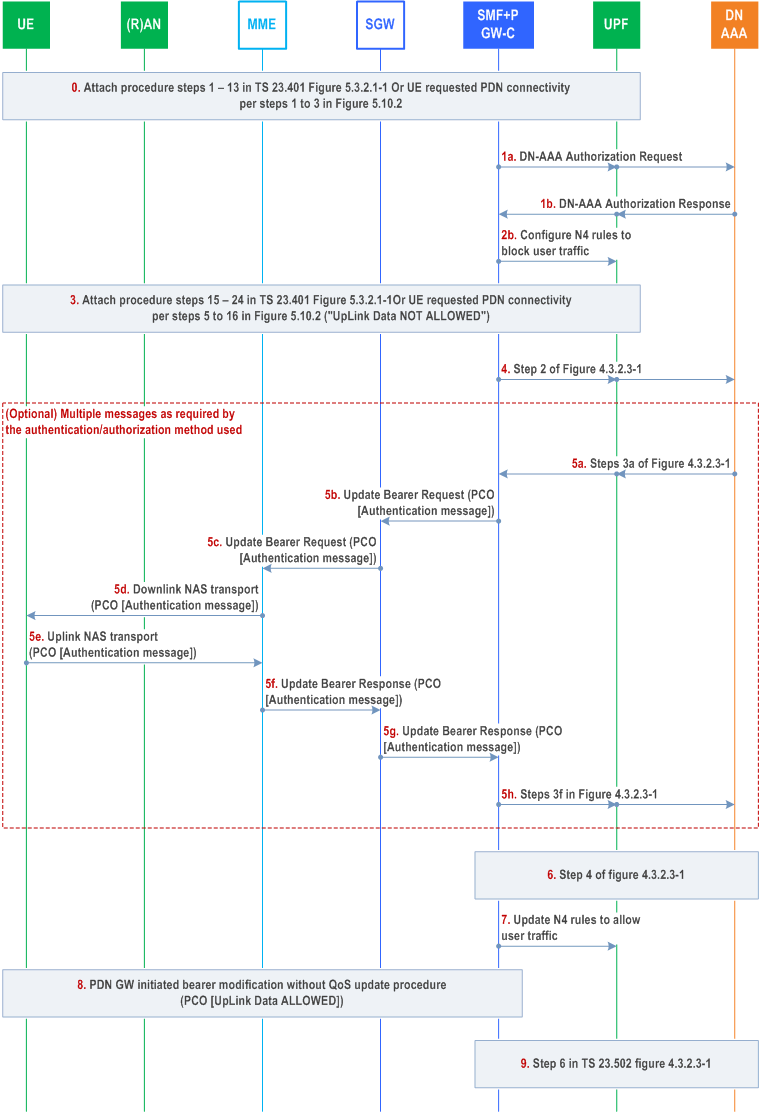
In the Figure H.2.1-1, the execution of the secondary authentication and authorization by DN-AAA is specified. The procedure assumes that:
- The APN is associated with the selection of a SMF+PGW-C to serve APN(s) that require secondary authentication and authorization by DN-AAA at PDN connection establishment.
- The SMF+PGW-C is configured with local policies indicating that the APN requires secondary authentication and authorization by DN-AAA at PDN connection establishment.

Step 0.
The DN-AAA Server may revoke the authorization for a PDN connection or update DN authorization data for a PDN connection. According to the request from DN-AAA Server, the SMF+PGW-C may release or update the PDN connection.
At any time after the PDN connection establishment, the DN-AAA Server or SMF+PGW-C may initiate Secondary Re-authentication procedure for the PDN connection as described in clause 4.3.2.3. Steps 4a-4h are performed to transfer the Secondary Re-authentication message between the DN-AAA Server and the UE. The Secondary Re-authentication procedure may start from step 4a (DN-AAA initiated Secondary Re-authentication procedure) or step 4b (SMF+PGW-C initiated Secondary Re-authentication procedure).
During Secondary Re-authentication, if the SMF+PGW-C receives an indication from the MME that the UE is unreachable then it informs the DN-AAA Server that UE is not reachable for re-authentication. Based on this indication from SMF+PGW-C, the DN-AAA Server may decide to keep the PDN connection or request to release it.
DN-AAA may initiate DN-AAA Re-authorization without performing re-authentication based on local policy. DN-AAA Re-authorization procedure may involve steps 5 and 6 of Figure H.2.1-1 above.
During Secondary Re-authentication/Re-authorization, if the SMF+PGW-C receives DN Authorization Profile Index and/or DN authorized Session AMBR, the SMF+PGW-C reports the received value(s) to the PCF (as described in TS 23.501) by triggering the Policy Control Request Trigger as described in TS 23.503.
As steps 1 - 13 of Figure 5.3.2.1-1 in TS 23.401 (Attach Request) or as steps 1 to 3 of Figure 5.10.2-1 in TS 23.401 (UE requested PDN connectivity) with following modifications: The UE may indicate in PCO its capability to support EAP-based secondary DN authentication over EPC if the UE included the PDU Session ID in PCO. The UE may also include the DN-specific identity.
Step 1.
The SMF+PGW-C gets subscription data from UDM as defined in step 4 of Figure 4.3.2.2.1-1 (not shown in Figure H.2.1-1). The procedure assumes that SMF configuration or subscription data from UDM require EAP-based secondary authentication and authorization by DN-AAA.
Secondary DN authorization may be invoked as described in TS 29.561. During this step the DN-AAA may provide an IP address for the UE and other DN authorization data as described in clause 5.6.6 of TS 23.501.
Step 2a.
If dynamic PCC is to be used for the PDU Session, the SMF+PGW-C performs an SM Policy Association Establishment procedure as defined in clause 4.16.4 and if Secondary DN authorization has been invoked in step 1, provides to the PCF the PDN Connection parameters received from the DN AAA at step 1 as described in step 5 of Figure 4.3.2.3-1. In this step the SMF+PGW-C may retrieve the PDU Session related policy information and the PCC rule(s) from the PCF, e.g. the authorized Session AMBR.
Step 2b.
UPF selection and N4 session establishment is executed with the difference that the SMF+PGW-C configures the UPF+PGW-U to block any UE traffic over the PDN Connection (until the Secondary DN authentication and authorization has been done and is successful).
Step 3.
Steps 15-24 in Figure 5.3.2.1-1 of TS 23.401 or steps 5-16 in Figure 5.10.2-1 of TS 23.401.
During the Attach procedure, at step 15 in Figure 5.3.2.1-1 of TS 23.401 or during UE requested PDN connectivity in step 5 in Figure 5.10.2-1 of TS 23.401, the SMF+PGW-C includes in PCO, an Indication to the UE that "UpLink Data is NOT ALLOWED" on the PDN connection. The UE shall not send Uplink data to the network, until it receives an indication further from the network that "UpLink Data is ALLOWED".
Step 4.
[Conditional] The PGW-C+SMF initiates EAP-based authentication by sending EAP-Request as described in step 2 of Figure 4.3.2.3-1.
Step 5.
Multiple round-trip messages as required by the authentication method used by DN-AAA may follow. The PCO including the authentication message from the DN-AAA is transferred to the UE by the SMF+PGW-C in Update Bearer Request and then over S1 by Downlink NAS Transport (steps 4b-4d). The response from the UE is transferred to the SMF+PGW-C in an Uplink NAS Transport over S1 and Update Bearer Response (steps 4e-4g) over EPS.
Step 6.
Secondary authentication and authorization by DN-AAA procedure continues as described in step 4 of Figure 4.3.2.3-1.
Step 7.
The SMF+PGW-C updates the N4 rules in the UPF+PGW-U to allow traffic over the PDN Connection. If dynamic PCC is to be used for the PDU Session and the SMF+PGW-C received DN Authorization information from the DN-AAA as part of step 5 or 6 that is different compared to the value received in step 2, the SMF+PGW-C contacts the PCF to update the PDN Connection as described in step 5 of Figure 4.3.2.3-1
Step 8.
The SMF+PGW-C updates the UE by invoking the PDN GW initiated bearer modification without QoS update procedure (Figure 5.4.3-1 of TS 23.401) initiated by sending an Update Bearer Request message to the SGW. The PCO includes an indication that "UpLink Data is ALLOWED". The UE confirms the update (see clause 5.4.3 of TS 23.401).
If the UE IP address is to be delivered to the UE over user plane (via Router advertisement or DHCP) then the UE IP address is only delivered to the UE after step 8.
Step 9.
As in step 6 of Figure 4.3.2.3-1.
I Member UE selection without the NEF assistance at the AF |R18| p. 914
This informative Annex describes an example of the procedure that AF selects the FL members by collecting network exposure information in case that no NEF is present in the 5GS. In this example, QoS Monitoring is used for FL Member UE selection.
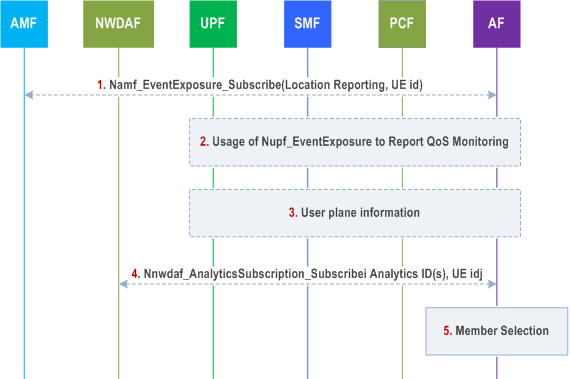
Network exposure information as described in clause 4.15 of TS 23.502, e.g. UE location reporting from the AMF, user plane information from the UPF and data analytics from NWDAF may be collected and used to assist the AF in application layer Member UE selection e.g. assist in the selection of Member UEs participating in a federating learning operation.

Step 1.
[Optional] The AF requests the location reporting of the UEs from the AMF by invoking existing Namf_EventExposure_Subscribe (Location Reporting).
Step 2.
[Optional] The AF initiates direct notification of QoS Monitoring procedure for delay information for the UEs in the candidate list, as defined in steps 1a-5 of clause 6.4.2.1 of TS 23.548.
Step 3.
[Optional] The AF requests user plane information, e.g. Throughput UL/DL, Packet transmission, Packet retransmission, for the UEs in the candidate list from UPF.
Step 4.
[Optional] The AF requests analytics from NWDAF by invoking the Nnwdaf_AnalyticsSubscription_Subscribe service operation, such as UE Communication, User Data Congestion Analytics, WLAN performance analytics per UE, etc. as defined in TS 23.288.
Step 5.
The AF selects members, e.g. for application layer Member UE selection for FL, based on the information collected in steps 1-4.
J Support for Personal IoT Networks |R18| p. 915
J.1 Procedure for PIN service p. 915

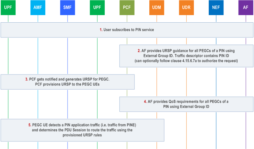
PIN is a subscribed service, and a user needs to coordinate with the Mobile Network Operator to subscribe for PIN service. When a user subscribes for a PIN, the subscription data includes the (DNN, S NSSAI) combination allocated by the MNO for the PIN service. The PEGC(s) are then provisioned with appropriate URSP rules to enable the PEGC UE to route the PIN traffic using the (DNN, S NSSAI) combination allocated for the PIN. Figure J.1-1 provides a high level procedure for PIN service.
Step 1.
When 5G VN Group is not used for a PIN and if the PIN contains more than one PEGCs, then the AF request for URSP guidance and QoS requirements is targeted to each individual PEGCs that are part of the PIN.
Step 1 is performed using O&M.
A user subscribes to the Mobile Network Operator (MNO) for PIN service. The user provides the list of PEGC(s) that are part of the PIN. The MNO verifies the request, performs necessary checks e.g. whether the UEs are allowed to act as PEGC, whether all the requested PEGC are part of the same UDM group etc. If the request is authorized by the MNO, the MNO:
Step 2.
- allocates a dedicated (DNN, S NSSAI) combination for the PIN;
- if the PIN has a single PEGC, then updates the PEGC subscription with the (DNN, S NSSAI) combination allocated for the PIN;
- if the PIN has more than one PEGC and 5G VN Group is used for a PIN, then creates a group subscription following the 5G VN group management principles as specified in clause 5.29.2 of TS 23.501. The information on the External Group ID and associated (DNN, S-NSSAI) combination is provided to the AF for PIN;
- if local switching is required, configures in the SMF set and/or in the NRF that the DNN allocated for the PIN is served by a specific SMF set.
For routing PIN traffic by the PEGC, the AF for PIN provides guidance for URSP generation to the 5GC. The AF for PIN uses a UE ID (i.e. GPSI) as the target UE if the PIN contains a single PEGC. If the PIN contains more than one PEGC and 5G VN Group is used for a PIN, then the AF uses External Group ID as the target UEs for providing URSP guidance to the 5GC. The AF request contains (DNN, S NSSAI) combination allocated to the user for the PIN service and the traffic descriptor components in the URSP rule request from the AF for PIN contains the PIN ID.
The NEF authorizes the request received from the AF for PIN and stores the information in the UDR as "Application Data".
The NEF can use the procedure for authorization of service specific parameter provisioning as specified in clause 4.15.6.7a to authorize the AF request by the UDM. In this case:
Step 3.
- if the request is for an individual UE, the UDM checks if the (DNN, S NSSAI) combination in the AF request is allowed for the UE;
- if the request is for a group of UEs and 5G VN Group is used for a PIN, the UDM checks whether the group related data (e.g. (DNN, S-NSSAI) combination group related data, see table 4.15.6.3b-1) is authorized for the group.
The PCF receives a Nudr_DM_Notify notification of data change from the UDR, generates the URSP rules and initiates UE Policy delivery as specified in clause 4.2.4.3 to provision the URSP rules in the PEGC(s). For routing of PIN traffic by the PEGC(s), the URSP policies provided to the PEGC UE(s) contain URSP rule with PIN ID as traffic descriptor.
Step 4.
The AF for PIN provides QoS requirements for the PIN traffic following procedures for AF requested QoS for a UE or group of UEs not identified by a UE address as specified in clause 4.15.6.14.
Step 5.
When the PEGC(s) detect PIN traffic, it uses the provisioned URSP rules to identify PDU session to route the traffic as specified in clause 6.6.2.3 of TS 23.503. The 5GC further performs session management and user plane management as described in Annex P, clause P.2 of TS 23.501.