Content for TS 23.502 Word version: 19.2.0
1…
4.2.2.2.2
4.2.2.2.3…
4.2.2.3…
4.2.3…
4.2.3.3
4.2.4…
4.2.6
4.2.7…
4.2.9…
4.2.11…
4.2.11.5…
4.3…
4.3.2.2.2
4.3.2.2.3…
4.3.3…
4.3.3.3
4.3.4…
4.3.4.3
4.3.5…
4.3.5.2…
4.3.5.4…
4.3.5.6…
4.3.6…
4.4…
4.5…
4.9…
4.9.1.3…
4.9.2…
4.11…
4.11.1…
4.11.1.2.2
4.11.1.2.3
4.11.1.3…
4.11.1.3.3…
4.11.1.4…
4.11.1.5…
4.11.2…
4.11.3…
4.12…
4.12.6…
4.12a…
4.12b…
4.13…
4.13.4…
4.13.6…
4.14…
4.15…
4.15.3.2.5…
4.15.4…
4.15.6…
4.15.6.7…
4.15.6.13…
4.15.6.14…
4.15.9…
4.15.9.4…
4.15.13…
4.15.13.4…
4.16…
4.16.4…
4.16.8…
4.16.11…
4.16.14…
4.16.15…
4.17…
4.17.9…
4.18…
4.19…
4.22…
4.23…
4.23.7…
4.23.7.3.3
4.23.7.3.4…
4.23.9…
4.23.9.4…
4.23.11…
4.24…
4.25…
4.25.6…
4.26…
5…
5.2.3…
5.2.5…
5.2.6…
5.2.7…
5.2.8…
5.2.9…
5.2.12…
5.2.18…
A…
E…
F…
G
H…
4.3.2.2.3 SMF selection
4.3.2.2.3.1 General
4.3.2.2.3.2 Non-roaming and roaming with local breakout
4.3.2.2.3.3 Home routed roaming
4.3.2.2.4 Multiple PDU Sessions towards the same DNN and S-NSSAI
4.3.2.3 Secondary authorization/authentication by an DN-AAA Server during the PDU Session establishment
4.3.2.4 Support of L2TP
...
...
4.3.2.2.3 SMF selection p. 150
4.3.2.2.3.1 General p. 150
The SMF selection function, as described in clause 6.3.2 of TS 23.501, is supported by the AMF and is used to allocate an SMF that manages the PDU Session.
The SMF selection function described in this clause does not apply to the selection of an SMF for Emergency services. For SMF selection for Emergency services is described in clause 5.16.4.5 of TS 23.501.
Two main branches of deployment scenarios to consider:
- Non-roaming and roaming with local breakout, see clause 4.3.2.2.3.2
- Home routed roaming, see clause 4.3.2.2.3.3
4.3.2.2.3.2 Non-roaming and roaming with local breakout p. 150
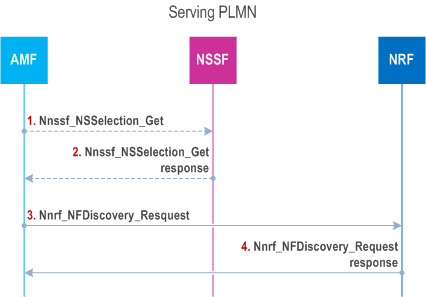
This procedure may be skipped altogether if SMF information is available in the AMF by other means (e.g. locally configured); otherwise:
- when the serving AMF is aware of the appropriate NRF to be used to select NFs/services within the corresponding Network Slice instance based on configuration or based on the Network Slice selection information received during Registration, only steps 3 and 4 in the following procedure are executed as described in Figure 4.3.2.2.3.2-1;
- when the serving AMF is not aware of the appropriate NRF to be used to select NFs/services within the corresponding Network Slice instance, all steps in the following procedure are executed as described in Figure 4.3.2.2.3.2-1.
Step 1.
The AMF invokes the Nnssf_NSSelection_Get service operation from the NSSF in serving PLMN with the S-NSSAI of the Serving PLMN from the Allowed NSSAI or Partially Allowed NSSAI requested by the UE, PLMN ID of the SUPI, TAI of the UE and the indication that the request is within a procedure of PDU Session establishment in either the non-roaming or roaming with local breakout scenario.
Step 2.
The NSSF in serving PLMN selects the Network Slice instance, determines and returns the appropriate NRF to be used to select NFs/services within the selected Network Slice instance and optionally may return a NSI ID corresponding to the Network Slice instance.
Step 3.
AMF queries the appropriate NRF in serving PLMN (including the scenario where SMF instances reside in a target PLMN as specified in clause 4.2.3 and clause 6.2.6.1 of TS 23.501) by issuing the Nnrf_NFDiscovery_Request including at least the S-NSSAI of the Serving PLMN for this PDU Session from the Allowed NSSAI or Partially Allowed NSSAI, PLMN ID of the SUPI, DNN and possibly NSI ID if the AMF has stored an NSI ID for the S-NSSAI of the Serving PLMN for this PDU Session from the Allowed NSSAI or Partially Allowed NSSAI.
Step 4.
The NRF in serving PLMN provides to the AMF, e.g. FQDN or IP address, of a set of the discovered SMF instance(s) or Endpoint Address(es) of SMF service instance(s) in Nnrf_NFDiscovery_Request response message and possibly an NSI ID for the selected Network Slice instance corresponding to the S-NSSAI for subsequent NRF queries.
4.3.2.2.3.3 Home routed roaming p. 148
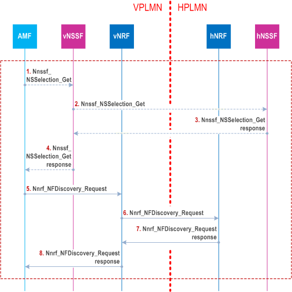
The discovery and selection of the SMF in VPLMN is performed in the same way as for non-roaming and roaming with local breakout (see clause 4.3.2.2.3.2). The discovery and selection of the H-SMF in HPLMN, including the case of the Indirect Network Sharing scenario as described in clause 5.18 and clause 6.3.2 of TS 23.501, is performed by means of either using NSSFs in VPLMN and HPLMN to discover a NRF in HPLMN (hNRF) or by having the hNRF configured in VPLMN. Which of these two options to use is based on local configuration in the VPLMN. The configuration depends on Service Level Agreements between the operators.
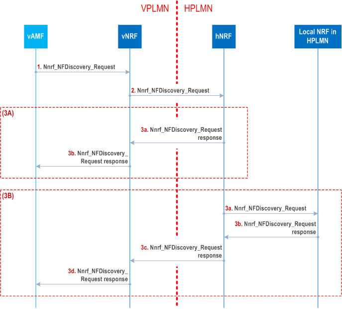
The discovery and selection of the H-SMF in HPLMN is performed by means of the procedure depicted in Figure 4.3.2.2.3.3-1 for the option where NSSFs are used for hNRF discovery. In this case the steps 1 to 4 in Figure 4.3.2.2.3.3-1 are required. In the option where VPLMN are having hNRF configured, then NRF in VPLMN (vNRF) has the endpoint(s) of the Nnrf_NFdiscovery service(s) of the hNRF(s) as described in Figure 4.3.2.2.3.3-2.
Step 1.
The steps 5-8 below apply SMF discovery of the general procedure for NF/NF service discovery across PLMNs in the case of discovery made by NF service consumer defined in clause 4.17.5.
Based on the operator's configuration, if the AMF is not aware of the appropriate NRF to be used to discover NFs/NF services in the HPLMN, the AMF invokes the Nnssf_NSSelection_Get service operation from the NSSF in VPLMN (vNSSF) with the VPLMN S-NSSAI from the Allowed NSSAI or Partially Allowed NSSAI requested by the UE for this PDU Session, the HPLMN S-NSSAI that maps to the VPLMN S-NSSAI, PLMN ID of the SUPI, the TAI of the UE and the indication that the request is within a procedure of PDU Session establishment in the home-routed roaming scenario.
Step 2.
If slicing configuration information for the S-NSSAI in the HPLMN is not available (e.g. the vNSSF has no cached information), the vNSSF invokes the Nnssf_NSSelection_Get service operation from NSSF of the HPLMN (hNSSF) according to the PLMN ID of the SUPI by including the HPLMN S-NSSAI. The vNSSF may be configured with the address(es) of the Nnssf_NSSelection_Get service(s) of the hNSSF.
Step 3.
The NSSF in HPLMN may include the NSI ID, if needed, for the Network Slice instance in HPLMN selected for the corresponding S-NSSAI of the HPLMN in the Nnssf_NSSelection_Get response. The NSSF in HPLMN also includes the appropriate hNRF to be used to discover NFs/NF services within HPLMN in the Nnssf_NSSelection_Get response.
Step 4.
The vNSSF includes in the Nnssf_NSSelection_Get response all the information that has been received from the NSSF in HPLMN in the response to the AMF.
Step 5.
The second option is depicted in Figure 4.3.2.2.3.3-2.
The AMF queries the vNRF using the Nnrf_NFDiscovery_Request by including PLMN ID of the SUPI, the serving PLMN ID, DNN, HPLMN S-NSSAI, the hNRF (if discovered in steps 1-4 or cached) and possibly an HPLMN NSI ID for the selected Network Slice instance corresponding to the HPLMN S-NSSAI if available in the AMF (obtained from the HPLMN NSSF in steps 3 and 4 or cached from a previous H-NSSF query).
In the case of Indirect Network Sharing, the AMF may also include e.g. following query parameters, the service area/serving scope/preferred locality of SMF based on UE location as described in clause 6.3.2 of TS 23.501.
Step 6.
The vNRF invokes the Nnrf_NFDiscovery_Request service operation from hNRF (address aquired in step 5, or configured) according the procedure in Figure 4.17.4-1 to get the NF profiles of candidate H-SMF instance(s) in the HPLMN. As the vNRF sends an Nnrf_NFDiscovery request on behalf of the AMF, the vNRF shall not replace the information of the requesting NF ID, i.e. AMF ID, in the Nnrf_NFDiscovery_Request messag. If hNRF does not hold the NF profiles of the candidate H-SMF instances, hNRF may further interrogate other NRF(s) of the HPLMN to discovery H-SMF instances. For further information about NRF-NRF interactions, see clauses 5.3.2.2.4 and 5.3.2.2.5 of TS 29.510.
Step 7-8.
The hNRF provides to the AMF (including the scenario where SMF instances reside in a target PLMN for traffic from certain UEs as specified in clause 4.2.4 and clause 6.2.6.1 of TS 23.501), via vNRF, the NF profiles of the discovered H-SMF instance(s) in Nnrf_NFDiscovery_Request response message, which may also include an NSI ID for the selected Network Slice instance corresponding to the S-NSSAI of the HPLMN, which can be used for subsequent NRF queries.
Step 1.
The steps 3a-3d below apply SMF discovery of the general procedure for NF/NF service discovery across PLMNs in the case of discovery made by NF service consumer defined in clause 4.17.5.
Depending on the available information and based on configuration, the hNRF may either execute steps in 3(A) or in 3(B).
Based on the operator's configuration, the AMF queries the vNRF with PLMN ID of the SUPI, PLMN ID of the serving PLMN, DNN, the HPLMN S-NSSAI that maps to the S-NSSAI from the Allowed NSSAI or Partially Allowed NSSAI of the Serving PLMN the UE has requested, the endpoint(s) of the discovery service(s) of hNRF if available and if applicable and available, an HPLMN NSI ID (if the AMF has stored hNRF information and if applicable and available, an HPLMN NSI ID for the selected Network Slice instance corresponding to the S-NSSAI of the HPLMN) and DNN.
In the case of Indirect Network Sharing, the AMF may also include e.g. following query parameters, service area/serving scope/preferred locality of SMF based on UE location as described in clause 6.3.2 of TS 23.501.
Step 2.
The vNRF queries, on behalf of the AMF in VPLMN, the hNRF identified by means of the PLMN ID of the SUPI (if no endpoint address of hNRF discovery service is received from the AMF, the vNRF determines the endpoint address of hNRF based on local configuration using information received in step 1). The vNRF in VPLMN sends an Nnrf_NFDiscovery request to the hNRF according to the procedure in Figure 4.17.4-1 to get the NF profiles of candidate H-SMF(s). As the vNRF sends an Nnrf_NFDiscovery request on behalf of the AMF, the vNRF shall not replace the information of the requesting NF, i.e. AMF ID, in the Nnrf_NFDiscovery_Request message.
Step 3(A).
The hNRF provides to the AMF, via vNRF, the NF profile(s) of the discovered SMF instance(s) and possibly an NSI ID for the selected HPLMN part of the Network Slice instance corresponding to the S-NSSAI of the HPLMN for subsequent NRF queries in Nnrf_NFDiscovery_Request response message(steps 3a and 3b).
Step 3(B).
The hNRF queries, on behalf of the AMF, another NRF (e.g. a slice level NRF in HPLMN or a NRF in a target PLMN for the scenario where NF instances reside in that target PLMN for certain UEs as specified in clause 4.2.4 and clause 6.2.6.1 of TS 23.501); the queried NRF provides NF profiles of SMF instance(s) and possibly an NSI ID for the selected HPLMN part of the Network Slice instance corresponding to the S-NSSAI of the HPLMN for subsequent NRF queries (steps 3a and 3b) that the hNRF returns, via vNRF, to the AMF (steps 3c and 3d).
4.3.2.2.4 Multiple PDU Sessions towards the same DNN and S-NSSAI |R16| p. 154
A UE may establish multiple PDU Sessions associated with the same DNN and S-NSSAI and the AMF may select the same SMF or different SMFs as specified in clause 6.3.2 of TS 23.501.
During PDU Session establishment, the AMF checks if the SMF selection subscription data indicates that the same SMF is required for multiple PDU Sessions and if required, the AMF checks if any SMF is already selected for the same DNN and S-NSSAI, if so, the same SMF will be used for the additional PDU Session.
4.3.2.3 Secondary authorization/authentication by an DN-AAA Server during the PDU Session establishment p. 154
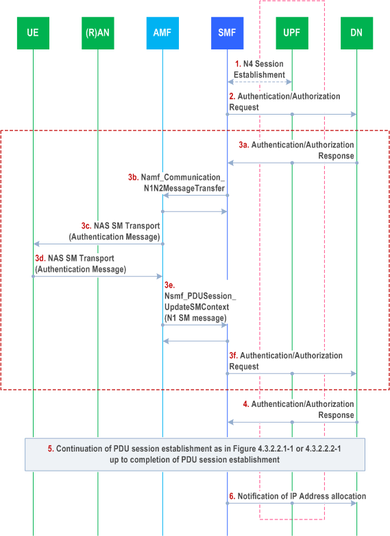
The PDU Session establishment authentication/authorization is optionally triggered by the SMF during a PDU Session establishment and performed transparently via a UPF or directly with the DN-AAA Server without involving the UPF if the DN-AAA Server is located in the 5GC and reachable directly, as described in clause 5.6.6 of TS 23.501.
In the case of Home Routed Roaming, unless specified otherwise, the SMF in the information flow defined in this clause is the H-SMF.
Step 0.
Later on the SMF notifies the DN-AAA if the DN-AAA had requested to get notifications about:
The SMF determines that it needs to contact the DN-AAA Server. The SMF identifies the DN-AAA Server based on local configuration or using the DN-specific identity (TS 33.501) provided by the UE inside the SM PDU DN Request Container provided by the UE in the PDU Session Establishment request or inside the EAP message in the PDU Session Authentication Complete message (TS 24.501).
Step 1.
If there is no existing N4 session that can be used to carry DN-related messages between the SMF and the DN, the SMF selects a UPF and triggers N4 session establishment.
Step 2.
The SMF initiates the authentication procedure with the DN-AAA via the UPF to authenticate the DN-specific identity provided by the UE as specified in TS 29.561.
When available, the SMF provides the GPSI in the signalling exchanged with the DN-AAA.
The UPF transparently relays the message received from the SMF to the DN-AAA Server.
Step 3a.
The DN-AAA Server sends an Authentication/Authorization message towards the SMF. The message is carried via the UPF.
Step 3b.
Transfer of DN Request Container information received from DN-AAA towards the UE.
In non-roaming and LBO cases, the SMF invokes the Namf_Communication_N1N2MessageTransfer service operation on the AMF to transfer the DN Request Container information within N1 SM information sent towards the UE.
In the case of Home Routed roaming, the H-SMF initiates a Nsmf_PDUSession_Update service operation to request the V-SMF to transfer DN Request Container to the UE and the V-SMF invokes the Namf_Communication_N1N2MessageTransfer service operation on the AMF to transfer the DN Request Container information within N1 SM information sent towards the UE. In Nsmf_PDUSession_Update Request, the H-SMF additionally includes the H-SMF SM Context ID.
Step 3c.
The AMF sends the N1 NAS message to the UE
Step 3d-3e.
Transfer of DN Request Container information received from UE towards the DN-AAA.
When the UE responds with a N1 NAS message containing DN Request Container information, the AMF informs the SMF by invoking the Nsmf_PDUSession_UpdateSMContext service operation. The SMF issues an Nsmf_PDUSession_UpdateSMContext response.
In the case of Home Routed roaming, the V-SMF relays the N1 SM information to the H-SMF using the information of PDU Session received in step 3b via a Nsmf_PDUSession_Update service operation.
Step 3f.
The SMF (In HR case it is the H-SMF) sends the content of the DN Request Container information (authentication message) to the DN-AAA Server via the UPF.
Step 3 may be repeated until the DN-AAA Server confirms the successful authentication/authorization of the PDU Session.
Step 4.
The DN-AAA Server confirms the successful authentication/authorization of the PDU Session. The DN-AAA Server may provide:
Step 5.
- an SM PDU DN Response Container to the SMF to indicate successful authentication/authorization;
- DN Authorization Data as defined in clause 5.6.6 of TS 23.501;
- a request to get notified with the IP address(es) allocated to the PDU Session and/or with N6 traffic routing information or MAC address(es) used by the UE for the PDU Session; and
- an IP address (or IPV6 Prefix) for the PDU Session.
The PDU Session establishment continues and completes. In the step 7b of the Figure 4.3.2.2.1-1, if the SMF receives the DN Authorization Profile Index in DN Authorization Data from the DN-AAA, it sends the DN Authorization Profile Index to retrieve the PDU Session related policy information (described in clause 6.4 of TS 23.503) and the PCC rule(s) (described in clause 6.3 of TS 23.503) from the PCF. If the SMF receives the DN authorized Session AMBR in DN Authorization Data from the DN-AAA, it sends the DN authorized Session AMBR within the Session AMBR to the PCF to retrieve the authorized Session AMBR (described in clause 6.4 of TS 23.503). For PDU Session of Ethernet type, the SMF may instruct the UPF to handle VLAN information of the Ethernet frames related with the PDU Session received and sent on N6 or N19 or internal interface, as described in clause 5.6.10.2 of TS 23.501.
Step 6.
If requested so in step 4 or if configured so by local policies, the SMF notifies the DN-AAA with the IP/MAC address(es) and/or with N6 traffic routing information allocated to the PDU Session together with the GPSI.
- allocation or release of an IPV6 Prefix for the PDU Session of IP type or addition or removal of source MAC addresses for the PDU Session of Ethernet type (e.g. using IPV6 multi-homing as defined in clause 5.6.4.3 of TS 23.501);
- Change of N6 traffic routing information.
4.3.2.4 Support of L2TP |R17| p. 157
L2TP may be used between UPF and the DN via N6 to carry traffic of a PDU Session, as defined in TS 23.501. The corresponding high level end to end signalling flow is described in this clause and further refined in TS 29.561. For the procedure described below, it is a prerequisite that the UE is already registered to the 5GC and both SMF and UPF support the L2TP feature.
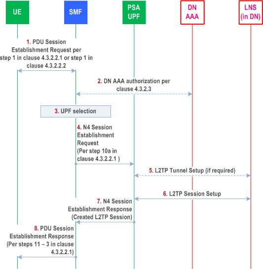
Step 1.
This step is the same as step 1 in clause 4.3.2.2.1 or step 1 in clause 4.3.2.2.2.
The PDU session establishment may include in the PCO information authentication information for PAP and/or CHAP.
Step 2.
The SMF may determine that an L2TP session is required for the PDU Session based on local configuration (e.g. related with DNN/S-NSSAI). The SMF may retrieve the L2TP Tunnel parameters from the DN-AAA Server, as described in clause 4.3.2.3, or be configured locally with L2TP Tunnel parameters.
The L2TP Tunnel parameters may include information such as the LNS addressing information (e.g. IP address or hostname), as defined in TS 29.561.
Step 3.
This step is the same as step 8 in clause 4.3.2.2.1 with the following additions:
If L2TP is required for the PDU Session, the SMF selects a UPF supporting L2TP.
Step 4.
This step is the same as step 10a in clause 4.3.2.2.1 with the following additions:
The SMF requests the UPF to setup an L2TP Session towards the L2TP server (LNS).
The SMF may send to the UPF as part of N4 signalling, L2TP Tunnel Information and L2TP Session Information to setup a L2TP session.
The L2TP Session Information includes specific information related to the PDU Session, e.g. a Calling Number which may be set to UE's SUPI, the Called Number for the L2TP Session which may be configured to contain the DNN, PAP/CHAP related parameters if included by the UE in PCO in step 1 etc. This information is defined in TS 29.561.
Step 5.
If needed the UPF may decide to setup a new L2TP Tunnel, as described in TS 29.561.
If the UPF decides to use an already existing L2TP Tunnel for the requested PDU Session from the SMF, it directly proceeds with step 6 below.
Step 6.
The UPF proceeds with L2TP Session setup towards the LNS, as described in TS 29.561.
If the SMF has requested the UPF to allocate the UE IP address in step 4, the UPF may retrieve the UE IP address from the LNS.
Step 7.
This step is the same as step 10b in clause 4.3.2.2.1 with the following additions:
The status of the L2TP Session setup is sent by the UPF to the SMF in a N4 Session Establishment Response. This may indicate information provided by the LNS Server for the UE such as the DNS server address, etc.
Step 8.
This step is the same as steps 11 - 13 in clause 4.3.2.2.1.