Content for TS 23.502 Word version: 19.2.0
1…
4.2.2.2.2
4.2.2.2.3…
4.2.2.3…
4.2.3…
4.2.3.3
4.2.4…
4.2.6
4.2.7…
4.2.9…
4.2.11…
4.2.11.5…
4.3…
4.3.2.2.2
4.3.2.2.3…
4.3.3…
4.3.3.3
4.3.4…
4.3.4.3
4.3.5…
4.3.5.2…
4.3.5.4…
4.3.5.6…
4.3.6…
4.4…
4.5…
4.9…
4.9.1.3…
4.9.2…
4.11…
4.11.1…
4.11.1.2.2
4.11.1.2.3
4.11.1.3…
4.11.1.3.3…
4.11.1.4…
4.11.1.5…
4.11.2…
4.11.3…
4.12…
4.12.6…
4.12a…
4.12b…
4.13…
4.13.4…
4.13.6…
4.14…
4.15…
4.15.3.2.5…
4.15.4…
4.15.6…
4.15.6.7…
4.15.6.13…
4.15.6.14…
4.15.9…
4.15.9.4…
4.15.13…
4.15.13.4…
4.16…
4.16.4…
4.16.8…
4.16.11…
4.16.14…
4.16.15…
4.17…
4.17.9…
4.18…
4.19…
4.22…
4.23…
4.23.7…
4.23.7.3.3
4.23.7.3.4…
4.23.9…
4.23.9.4…
4.23.11…
4.24…
4.25…
4.25.6…
4.26…
5…
5.2.3…
5.2.5…
5.2.6…
5.2.7…
5.2.8…
5.2.9…
5.2.12…
5.2.18…
A…
E…
F…
G
H…
4.11.1 N26 based Interworking Procedures
4.11.1.1 General
4.11.1.2 Handover procedures
4.11.1.2.1 5GS to EPS handover using N26 interface
...
...
4.11.1 N26 based Interworking Procedures p. 280
4.11.1.1 General p. 280
N26 interface is used to provide seamless session continuity for single registration mode UE.
Interworking between EPS and 5GS is supported with IP address preservation by assuming SSC mode 1. Interworking between EPS and 5GS is not supported for PDU Sessions with SSC mode 2 or SSC mode 3.
When the UE is served by the 5GC, during PDU Session establishment and GBR QoS Flow establishment, SMF+PGW-C performs EPS QoS mappings, from the 5G QoS parameters obtained from the PCF and allocates TFT with the PCC rules obtained from the PCF if PCC is deployed. Otherwise, EPS QoS mappings and TFT allocation are mapped by the SMF+PGW-C locally. The PGW+SMF ignores 5G QoS parameters that are not applicable to EPC (e.g. QoS Notification control). If a TFT is to be allocated for a downlink unidirectional EPS bearer mapped from a downlink only QoS Flow, the SMF+PGW-C shall allocate a TFT packet filter that effectively disallows any useful uplink packet as specified in TS 23.401. EPS Bearer IDs are allocated by the serving AMF requested by the SMF if the SMF determines that EPS Bearer IDs need to be assigned to the QoS Flows. For each PDU Session, EPS bearer IDs are allocated to the default EPS bearer and dedicated bearers. The SMF shall be able to determine the QoS flows that require EPS Bearer IDs, based on the QoS profile and operator policies.
When a new QoS Flow needs to be mapped to an EPS Bearer ID that has already been assigned for an existing QoS Flow, the SMF includes the already assigned EPS Bearer ID in the QoS Flow description sent to the UE.
If there is a possibility to run into a restriction regarding the number of TFT packet filters that can be allocated for the PDU Session,
- in the case that PCC is deployed, the PCF may include in the PCC rules the Precedence for TFT packet filter allocation parameter, which determines the order of the PCC rules in allocation of TFT packet filter(s) by the SMF+PGW-C.
- in the case that PCC is deployed but the Precedence for TFT packet filter allocation parameter is not received, or in the case that PCC is not deployed, the SMF+PGW-C makes the decision how to allocate TFT packet filter(s) based on operator policy or implementation.
- The UE considers the PDN connections released if those PDN connections were established over EPS and for which the UE has not received mapped 5GS QoS parameters from the network.
- The MME does not transfer to 5GS a PDN connection that does not support 5GS interworking, e.g. PDN connection was established on a stand-alone PGW, or 5GS interworking is restricted by subscription data.
4.11.1.2 Handover procedures p. 282
4.11.1.2.1 5GS to EPS handover using N26 interface p. 282
Figure 4.11.1.2.1-1 describes the handover procedure from 5GS to EPS when N26 is supported.
In the case of handover to a shared EPS network, the source NG-RAN determines a PLMN to be used in the target network as specified by TS 23.501. The source NG-RAN shall indicate the selected PLMN ID to be used in the target network to the AMF as part of the TAI sent in the HO Required message.
In the case of handover from a shared NG-RAN, the AMF may provide the MME with an indication that the 5GS PLMN is a preferred PLMN at later change of the UE to a 5GS shared networks.
During the handover procedure, as specified in clause 4.9.1.3.1, the source AMF shall reject any SMF+PGW-C initiated N2 request received since handover procedure started and shall include an indication that the request has been temporarily rejected due to handover procedure in progress.
Upon reception of a rejection for an SMF+PGW-C initiated N2 request(s) with an indication that the request has been temporarily rejected due to handover procedure in progress, the SMF+PGW-C behaves as specified in TS 23.401.
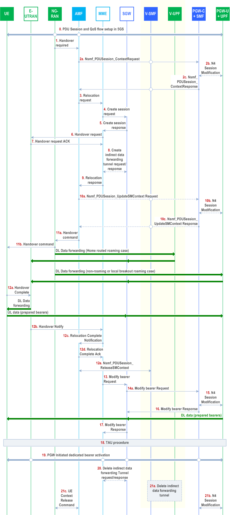
The procedure involves a handover to EPC and setup of default EPS bearer and dedicated bearers for QoS Flows that have EBI assigned, in EPC in steps 1-16 and re-activation, if required, of dedicated EPS bearers for non-GBR QoS Flows that have no EBI assigned, in step 19. This procedure can be triggered, for example, due to new radio conditions, load balancing or in the presence of QoS Flow for normal voice or IMS emergency voice, the source NG-RAN node may trigger handover to EPC.
For Ethernet and Unstructured PDU Session Types, the PDN Type Ethernet and non-IP respectively are used, when supported, in EPS.
When EPS supports PDN Type non-IP but not PDN type Ethernet, PDN type non-IP is used also for Ethernet PDU sessions. The SMF shall also set the PDN Type of the EPS Bearer Context to non-IP in this case. After the handover to EPS, the PDN Connection will have PDN Type non-IP, but it shall be locally associated in UE and SMF to PDU Session Type Ethernet or Unstructured respectively.
In the roaming home routed case, the SMF+PGW-C always provides the EPS Bearer ID and the mapped QoS parameters to UE. The V-SMF caches the EPS Bearer ID and the mapped QoS parameters obtained from H-SMF for this PDU session. This also applies in the case that the HPLMN operates the interworking procedure without N26.
Step 1.

Step 2a-2c.
Step 3.
Step 4-5.
Step 6.
Step 7-9.
Step 10a.
Step 10b.
Step 10c.
Step 11.
Step 12-12c.
Step 12d.
Step 12e.
Step 13.
Step 14a.
Step 15.
Step 16.
Step 17.
Step 18.
Step 19.
Step 20.
Step 21.
NG-RAN decides that the UE should be handed over to the E-UTRAN. If NG-RAN is configured to perform Inter RAT mobility due to IMS voice fallback triggered by QoS flow setup and request to setup QoS flow for IMS voice was received, NG-RAN responds indicating rejection of the QoS flow establishment because of mobility due to fallback for IMS voice via N2 SM information and triggers handover to E-UTRAN. The NG-RAN sends a Handover Required (Target eNB ID, Direct Forwarding Path Availability, Source to Target Transparent Container, inter system handover indication) message to the AMF. NG-RAN indicates bearers corresponding to the 5G QoS Flows for data forwarding in Source to Target Transparent Container.
If the source NG RAN and target E-UTRAN support RACS as defined in TS 23.501, the Source to Target transparent container need not carry the UE radio access capabilities (instead the UE Radio Capability ID is supplied from the CN to the target E-UTRAN). However, if the source NG-RAN has knowledge that the target E-UTRAN might not have a local copy of the Radio Capability corresponding to the UE Radio Capability ID (i.e. because the source NG-RAN had itself to retrieve the UE's Radio Capability from the AMF) then the source NG-RAN may also send some (or all) of the UE's Radio Capability to the target E-UTRAN (the size limit based on configuration). In the case of inter-PLMN handover, when the source NG-RAN and target E-UTRAN support RACS as defined in TS 23.501 and TS 23.401 and the source NG-RAN determines that the target PLMN does not support the UE Radio Capability ID assigned by the source PLMN based on local configuration, then the source NG-RAN includes the UE radio access capabilities in the Source to Target transparent container.
Direct Forwarding Path Availability indicates whether direct forwarding is available from the NG-RAN to the E-UTRAN. This indication from NG-RAN can be based on e.g. the presence of IP connectivity and security association(s) between the NG-RAN and the E-UTRAN.
If the handover is triggered due to Emergency fallback, the NG-RAN may forward the Emergency indication to the target eNB in the Source to Target Transparent Container and the target eNB allocates radio bearer resources taking received indication into account.
Step 2a-2c.
TThe AMF determines from the 'Target eNB Identifier' IE that the type of handover is Handover to E-UTRAN. The AMF selects an MME as described in clause 4.3.8.3 of TS 23.401.
The AMF determines for a PDU Session whether to retrieve context including mapped UE EPS PDN Connection from the V-SMF (in the case of HR roaming) or the SMF+PGW-C (in the case of non roaming or LBO roaming) as follows:
PDUSession_ContextRequest the AMF provides also the target MME capability to the V-SMF or the SMF+PGW-C to allow it to determine whether to include EPS Bearer context for Ethernet PDN Type or non-IP PDN Type or not.
When the AMF sends Nsmf_PDUSession_ContextRequest to the V-SMF or the SMF+PGW-C, the AMF indicates whether the target MME supports User Plane Integrity Protection with EPS.
When Nsmf_PDUSession_Context Request is received in the V-SMF or the SMF+PGW-C, the V-SMF or the SMF+PGW-C provides context that includes the mapped EPS PDN Connection as follows:
PDUSession_ContextRequest is received in PGW C+SMF, if the SMF+PGW-C determines that EPS Bearer Context can be transferred to EPS and the CN Tunnel Info for EPS bearer(s) have not been allocated before, the SMF+PGW-C sends N4 Session modification to the PGW-U+UPF to establish the CN tunnel for each EPS bearer and provides EPS Bearer Contexts to AMF, as described in step 8 of clause 4.11.1.4.1. The PGW-U+UPF is ready to receive the uplink packet from E-UTRAN.
This step is performed with all the SMF+PGW-Cs corresponding to PDU Sessions of the UE which are associated with 3GPP access and have at least one EBI(s) determined to be transferred to EPS.
In home routed roaming scenario, the UE's EPS PDN Contexts are obtained from the V-SMF. If Small Data Rate Control applies on PDU Session, the V-SMF retrieves the SM Context, including Small Rate Control Status information from the H-SMF using Nsmf_PDUSession_Context Request.
-
If the AMF determines that one or more of the EBI(s) can be transferred, the AMF sends Nsmf_
PDUSession_ to the V-SMF or SMF+PGW-C and includes in the message EBI value(s) if any that cannot be transferred.ContextRequest - The EBI values(s) that cannot be transferred is determined by the AMF if the target MME does not support 15 EPS bearers, i.e. the AMF determines the EBI values in range 1-4 as not to be transferred to EPS and if there are still more than 8 EBI values associated with PDU Sessions, the AMF then determines EBI value(s) not to be transferred to EPS based on S-NSSAI and ARP as specified in clause 5.17.2.2.1 of TS 23.501.
- The AMF does not retrieve the context for a PDU Session that cannot be transferred to EPS due to no EBI allocated, or allocated EBIs not transferrable, or combination of the two.
- If there is EBI list not to be transferred and the EBI value of the QoS Flow associated with the default QoS Rule is included in that list, the V-SMF or the SMF+PGW-C shall not return the PDN Connection context (which implies the whole PDU Session is not transferred to EPS), otherwise if the EBI value of the QoS Flow associated with the default QoS Rule is not included in EBI list not to be transferred, the V-SMF or PGW C+SMF shall not provide the EPS bearer context(s) mapped from QoS Flow(s) associated with the EBI list not to be transferred.
- For PDU Sessions with PDU Session Type Ethernet, if the UE and target MME supports Ethernet PDN type, the V-SMF or the PGW C+SMF provides Context for Ethernet PDN Type, otherwise if the target MME does not support Ethernet Type but support non-IP Type, the V-SMF or the PGW C+SMF provides Context for non-IP PDN Type. For PDU Sessions with PDU Session Type Unstructured, the V-SMF or the SMF+PGW-C provides Context for non-IP PDN Type.
- If the UP integrity protection policy for the EPS bearer context is set to "Required", the V-SMF or the PGW C+SMF shall not provide the EPS bearer context unless the MME capability indicates support for User Plane Integrity Protection with EPS and the UE supports User Plane Integrity Protection with EPS.
Step 3.
The AMF sends a Forward Relocation Request as in step 3 in clause 5.5.1.2.2 (S1-based handover, normal) in TS 23.401, with the following modifications and clarifications:
- Parameter "Return preferred" may be included. Return preferred is an optional indication by the MME of a preferred return of the UE to the 5GS PLMN at a later access change to a 5GS shared network. An MME may use this information as specified by TS 23.501.
- The SGW address and TEID for both the control-plane or EPS bearers in the message are such that target MME selects a new SGW.
- The AMF determines, based on configuration and the Direct Forwarding Path Availability, the Direct Forwarding Flag to inform the target MME whether direct data forwarding is applicable.
- The AMF includes the mapped SM EPS UE Contexts for PDU Sessions with and without active UP connections.
- Subject to operator policy if the secondary RAT access restriction condition is the same for EPS and 5GS, the AMF may set EPS secondary RAT access restriction condition based on the UE's subscription data.
Step 4-5.
Step 4 and 4a respectively in clause 5.5.1.2.2 (S1-based handover, normal) in TS 23.401.
Step 6.
Step 5 (Handover Request) in clause 5.5.1.2.2 (S1-based handover, normal) in TS 23.401 with the following modification:
- Handover Request may contain information Handover Restriction List with information about PLMN IDs as specified by clause 5.2a of TS 23.251 for eNodeB functions.
- The target eNB should establish E-RABs indicated by the list of EPS bearer to be setup provided by the MME, even if they are not included in the source to target container.
Step 7-9.
Step 5a through 7 in clause 5.5.1.2.2 (S1-based handover, normal) in TS 23.401.
Step 10a.
If data forwarding applies, the AMF sends the Nsmf_PDUSession_UpdateSMContext Request (data forwarding information) to the SMF+PGW-C. If multiple SMF+PGW-Cs serves the UE, the AMF maps the EPS bearers for Data forwarding to the SMF+PGW-C address(es) based on the association between the EPS bearer ID(s) and PDU Session ID(s). In home-routed roaming case, the AMF requests the V-SMF to create indirect forwarding tunnel if indirect forwarding applies.
Step 10b.
If indirect data forwarding applies, the SMF+PGW-C may select an intermediate PGW-U+UPF for data forwarding. The SMF+PGW-C maps the EPS bearers for Data forwarding to the 5G QoS flows based on the association between the EPS bearer ID(s) and QFI(s) for the QoS flow(s) in the SMF+PGW-C and then sends the QFIs, Serving GW Address(es) and TEID(s) for data forwarding to the PGW-U+UPF. The CN Tunnel Info is provided by the PGW-U+UPF to SMF+PGW-C in this response. In home-routed roaming case, the V-SMF selects the V-UPF for data forwarding.
The SMF+PGW-C deactivates PDU Set based handling at PGW-U+UPF if it is activated during the UE was registered to 5GS as described in clause 5.37.5.3 of TS 23.501.
Step 10c.
The SMF+PGW-C returns an Nsmf_PDUSession_UpdateSMContext Response (Cause, Data Forwarding tunnel Info, QoS flows for Data Forwarding). Based on the correlation between QFI(s) and Serving GW Address(es) and TEID(s) for data forwarding, the PGW-U+UPF maps the QoS flow(s) into the data forwarding tunnel(s) in EPC.
Step 11.
The AMF sends the Handover Command to the source NG-RAN (Transparent container (radio aspect parameters that the target eNB has set-up in the preparation phase), Data forwarding tunnel info, QoS flows for Data Forwarding). The source NG-RAN commands the UE to handover to the target Access Network by sending the HO Command. The UE correlates the ongoing QoS Flows with the indicated EPS Bearer IDs to be setup in the HO command. The UE locally deletes the PDU Session if the QoS Flow associated with the default QoS rule in the PDU Session does not have an EPS Bearer ID assigned. If the QoS Flow associated with the default QoS rule has an EPS Bearer ID assigned, the UE keeps the PDU Session (PDN connection) and for the remaining QoS Flow(s) that do not have EPS bearer ID(s) assigned, the UE locally deletes the QoS rule(s) and the QoS Flow level QoS parameters if any associated with those QoS Flow(s) and notifies the impacted applications that the dedicated QoS resource has been released. The UE deletes any UE derived QoS rules. The EPS Bearer ID that was assigned for the QoS flow of the default QoS rule in the PDU Session becomes the EPS Bearer ID of the default bearer in the corresponding PDN connection.
If indirect data forwarding is applied, Data forwarding tunnel info includes CN tunnel info for data forwarding per PDU session. For the QoS Flows indicated in the "QoS Flows for Data Forwarding", NG-RAN initiate data forwarding via to the PGW-U+UPF based on the CN Tunnel Info for Data Forwarding per PDU Session. Then the PGW-U+UPF maps data received from the data forwarding tunnel(s) in the 5GS to the data forwarding tunnel(s) in EPS and sends the data to the target eNodeB via the Serving GW.
If direct data forwarding is applied, Data forwarding tunnel info includes E-UTRAN tunnel info for data forwarding per EPS bearer. NG-RAN initiate data forwarding to the target E-UTRAN based on the Data Forwarding Tunnel Info for Data Forwarding per EPS bearer.
Step 12-12c.
Step 13 to step 14 from clause 5.5.1.2.2 (S1-based handover, normal) in TS 23.401 with the following clarification:
- The AMF requests the release of the PDU Session which is associated with 3GPP access and not expected to be transferred to EPC, i.e. the AMF requests the release of:
- PDU Session(s) whose corresponding SMF+PGW-C(s) are not contacted by AMF for SM context because the AMF determines that none of EBI(s) for the PDU Session can be transferred to EPS at step 2a; and
- PDU Session(s) for which the SM context retrieval failed at step 2c.
Step 12d.
The AMF acknowledges MME with Relocation Complete Ack message. A timer in AMF is started to supervise when resource in NG-RAN shall be released.
Step 12e.
In the case of home routed roaming, the AMF invokes Nsmf_PDUSession_ReleaseSMContext Request (V-SMF only indication) to the V-SMF. This service operation request the V-SMF to remove only the SM context in V-SMF, i.e. not release PDU Session context in the SMF+PGW-C.
If indirect forwarding tunnel(s) were previously established, the V-SMF starts a timer and releases the SM context on expiry of the timer. If no indirect forwarding tunnel has been established, the V-SMF immediately releases the SM context and its UP resources for this PDU Session in V-UPF locally.
Step 13.
Step 15 from clause 5.5.1.2.2 (S1-based handover, normal) in TS 23.401.
Step 14a.
Step 16 (Modify Bearer Request) from clause 5.5.1.2.2 (S1-based handover, normal) in TS 23.401 with the following clarification:
- If the PDU Session (PDN connection) has QoS Flows that do not have EPS bearer ID(s) assigned, or QoS Flow(s) for which the mapped EPS bearers are not included in Modify Bearer Request, the SMF+PGW-C deletes the PCC rule(s) associated with those QoS Flows and informs the PCF about the removed PCC rule(s). If there are QoS Flow(s) with PCC rule(s) that do not have allocated TFT packet filters, the SMF+PGW-C deletes those PCC rule(s) and informs the PCF about the removed PCC rule(s).
Step 15.
The SMF+PGW-C initiates a N4 Session Modification procedure towards the UPF+PGW-U to update the User Plane path, i.e. the downlink User Plane for the indicated PDU Session is switched to E-UTRAN. The SMF+PGW-C releases the resource of the CN tunnel for PDU Session in UPF+PGW-U.
Step 16.
Step 16a (Modify Bearer Response) from clause 5.5.1.2.2 (S1-based handover, normal) in TS 23.401. At this stage the User Plane path is established for the default bearer and the dedicated EPS bearers between the UE, target eNodeB, Serving GW and the PGW-U+UPF. The SMF+PGW-C uses the EPS QoS parameters as assigned for the dedicated EPS bearers during the QoS Flow establishment. SMF+PGW-C maps all the other IP flows to the default EPS bearer (see NOTE 4).
If indirect forwarding tunnel(s) were previously established, the SMF+PGW-C starts a timer, to be used to release the resource used for indirect data forwarding.
Step 17.
Step 17 from clause 5.5.1.2.2 (S1-based handover, normal) in TS 23.401.
Step 18.
The UE initiates a Tracking Area Update procedure as specified in step 18 of clause 5.5.1.2.2 (S1-based handover, normal) in TS 23.401.
This includes the deregistration of the old AMF for 3GPP access from the HSS+UDM as specified in clause 4.11.1.5.3. Any registration associated with the non-3GPP access in the old AMF is not removed (i.e. an AMF that was serving the UE over both 3GPP and non-3GPP accesses does not consider the UE as deregistered over non 3GPP access and will remain registered and subscribed to subscription data updates in UDM).
When the UE decides to deregister over non-3GPP access or the old AMF decides not to maintain a UE registration for non-3GPP access anymore, the old AMF then deregisters from UDM by sending a Nudm_UECM_Deregistration service operation, unsubscribes from Subscription Data updates by sending an Nudm_SDM_Unsubscribe service operation to UDM and releases all the AMF and AN resources related to the UE.
Step 19.
If PCC is deployed, the PCF may decide to provide the previously removed PCC rules to the SMF+PGW-C again thus triggering the SMF+PGW-C to initiate dedicated bearer activation procedure. This procedure is specified in clause 5.4.1 of TS 23.401 with modification captured in clause 4.11.1.5.4. This step is applicable for PDN Type IP or Ethernet, but not for non-IP PDN Type.
Step 20.
Step 21 from clause 5.5.1.2.2 (S1-based handover, normal) in TS 23.401.
Step 21.
In the case of home routed roaming, at the expiry of the timer at V-SMF started at step 12e, the V-SMF locally releases the SM context and the UP resource for the PDU Session including the resources used for indirect forwarding tunnel(s) that were allocated at step 10.
In non-roaming or local breakout roaming, if SMF+PGW-C has started a timer in step 16, at the expiry of the timer, the SMF+PGW-C sends N4 Session Modification Request to PGW-U+UPF to release the resources used for the indirect forwarding tunnel(s) that were allocated at step 10.
When the timer set in step 12d expires, AMF also sends a UE Context Release Command message to the source NG RAN. The source NG RAN releases its resources related to the UE and responds with a UE Context Release Complete message.
![]()
![]()
![]()