Content for TS 23.502 Word version: 19.2.0
1…
4.2.2.2.2
4.2.2.2.3…
4.2.2.3…
4.2.3…
4.2.3.3
4.2.4…
4.2.6
4.2.7…
4.2.9…
4.2.11…
4.2.11.5…
4.3…
4.3.2.2.2
4.3.2.2.3…
4.3.3…
4.3.3.3
4.3.4…
4.3.4.3
4.3.5…
4.3.5.2…
4.3.5.4…
4.3.5.6…
4.3.6…
4.4…
4.5…
4.9…
4.9.1.3…
4.9.2…
4.11…
4.11.1…
4.11.1.2.2
4.11.1.2.3
4.11.1.3…
4.11.1.3.3…
4.11.1.4…
4.11.1.5…
4.11.2…
4.11.3…
4.12…
4.12.6…
4.12a…
4.12b…
4.13…
4.13.4…
4.13.6…
4.14…
4.15…
4.15.3.2.5…
4.15.4…
4.15.6…
4.15.6.7…
4.15.6.13…
4.15.6.14…
4.15.9…
4.15.9.4…
4.15.13…
4.15.13.4…
4.16…
4.16.4…
4.16.8…
4.16.11…
4.16.14…
4.16.15…
4.17…
4.17.9…
4.18…
4.19…
4.22…
4.23…
4.23.7…
4.23.7.3.3
4.23.7.3.4…
4.23.9…
4.23.9.4…
4.23.11…
4.24…
4.25…
4.25.6…
4.26…
5…
5.2.3…
5.2.5…
5.2.6…
5.2.7…
5.2.8…
5.2.9…
5.2.12…
5.2.18…
A…
E…
F…
G
H…
4.3.5.6 Change of additional PDU Session Anchor for IPv6 multi-homing or UL CL
4.3.5.7 Simultaneous change of Branching Point or UL CL and additional PSA for a PDU Session
4.3.5.8 Ethernet PDU Session Anchor Relocation
...
...
4.3.5.6 Change of additional PDU Session Anchor for IPv6 multi-homing or UL CL p. 192
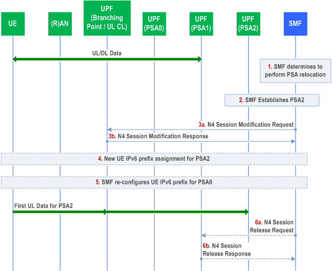
The following procedure is triggered by an SMF when the SMF needs to modify IPv6 multi-homing or UL CL rule (i.e. traffic filter in the Branching Point or the UL CL) in order to move the some or whole traffic flows of the existing additional PDU Session Anchor which was established by the IPv6 multi-homing or the UL CL operations (i.e. PSA1 in Figure 4.3.5.6-1) to a new additional PDU Session Anchor (i.e. PSA2 in Figure 4.3.5.6-1) which is established under the same Branching Point or UL CL for a UE where the UE already has a PDU Session Anchor which was established before the event of Branching Point or UL CL insertion (i.e. PSA0 in Figure 4.3.5.6-1). This procedure establishes a new additional PDU Session Anchor (i.e. PSA2) and conditionally releases the existing additional PDU Session Anchor (i.e. PSA1), while modifying IPv6 multi-homing or UL CL rule in the same Branching Point or UL CL under controlled by the same SMF.

Step 1.
The SMF decides to change one additional PSA of a PDU Session with IPv6 multi-homing or UL CL, due to events that may benefit from such change or upon request from an Application Function.
Step 2.
If the runtime coordination between 5GC and AF is enabled based on local configuration, according to the indication of "AF acknowledgment to be expected" included in AF subscription to SMF events, the SMF sends an early notification to the AF after PSA2 is selected and waits for a notification response from the AF before configuring the PSA2. If the SMF receives a negative notification response from the AF, the SMF may stop the procedure. This is defined in Figure 4.3.6.3-1.
The SMF sends an N4 Session Establishment Request to PSA2 and provides the tunnel ID of Branching Point or UL CL, Packet detection, enforcement and reporting rules to be installed on the PSA2 for this PDU Session. The SMF may also indicate local PSA2 to buffer the uplink data.
The PSA2 acknowledges by sending an N4 Session Establishment Response. The tunnel ID of PSA2 is provided to the SMF in this step.
In the case of IPv6 multi-homing PDU Session, a new IPv6 prefix corresponding to PSA2 is allocated (by the SMF or by the UPF depending on the deployment) and if the PCF has subscribed to the IP allocation/release event, the SMF performs the Session Management Policy Modification Procedure as defined in clause 4.16.5 to provide the new allocated IPv6 prefix to the PCF.
Step 3a.
In the case of PDU session with UL CL, if the runtime coordination between 5GC and AF is enabled based on local configuration, according to the indication of "AF acknowledgment to be expected" included in AF subscription to SMF events, the SMF sends a late notification to the AF and waits for a notification response from the AF. If the SMF receives a negative notification response from the AF, the SMF may stop the procedure. This is further defined in Figure 4.3.6.3-1.
The SMF sends an N4 Session Modification Request to the Branching Point or UL CL to update the UL traffic filter according to new allocated IPv6 prefix allocated to PSA 2 or the UL CL rules regarding to the traffic flows that the SMF tries to move from PSA1 to PSA2. The N4 Session Modification Request message contains the identifications of traffic filter that needs to be updated and the tunnel ID of PSA2.
Step 3b.
The Branching Point or the UL CL acknowledges by N4 Session Modification Response the Branching Point or when the UL CL successfully updates all the traffic filters that the SMF requests to modify.
Step 3c.
The SMF may also indicate PSA2 to stop buffering and start forwarding uplink data.
Step 4.
In the case of IPv6 multi-homing PDU Session, if the runtime coordination between 5GC and AF is enabled based on local configuration, according to the indication of "AF acknowledgment to be expected" included in AF subscription to SMF events, the SMF sends a late notification to the AF and waits for a notification response from the AF. If the SMF receives a negative notification response from the AF, the SMF may stop the procedure. This is further defined in Figure 4.3.6.3-1.
In the case of IPv6 multi-homing PDU Session, The SMF notifies the UE of the availability of the new IP prefix @ PSA2. This is performed using an IPv6 Router Advertisement message (RFC 4861). Also, the SMF sends IPv6 multi-homed routing rule along with the IPv6 prefix to the UE using an IPv6 Router Advertisement message (RFC 4191) as described in clause 5.8.2.2.2 of TS 23.501. The SMF may also indicate PSA2 to stop buffering and start forwarding uplink data.
Step 5.
In the case of IPv6 multi-homing PDU Session, The SMF may re-configure the UE for the original IP prefix @ PSA0,i.e. SMF sends IPv6 multi-homed routing rule along with the IPv6 prefix to the UE using an IPv6 Router Advertisement message (RFC 4191) as described in clause 5.8.2.2.2 of TS 23.501.
Step 6.
Step 6 occurs only if the Branching Point or UL CL does not have any traffic filter on the PDU Session which forwards a traffic flow to PSA1.
Step 6a.
The SMF sends an N4 Session Release Request with N4 session ID to PSA1. The PSA1 shall release all tunnel resources and contexts associated with the N4 session.
Step 6b.
PSA1 sends an N4 Session Release Response with N4 session ID to the SMF at the same moment that PSA1 successfully releases all tunnel resources and contexts associated with the N4 session.
4.3.5.7 Simultaneous change of Branching Point or UL CL and additional PSA for a PDU Session p. 193
Simultaneous change of UL CL or Branching Point and additional PSA can be performed after Xn based handover, N2 based handover and Service Request procedures.
The following procedure is triggered by SMF in order to change the Branching Point or the UL CL and additional PSA serving a PDU Session for a UE.

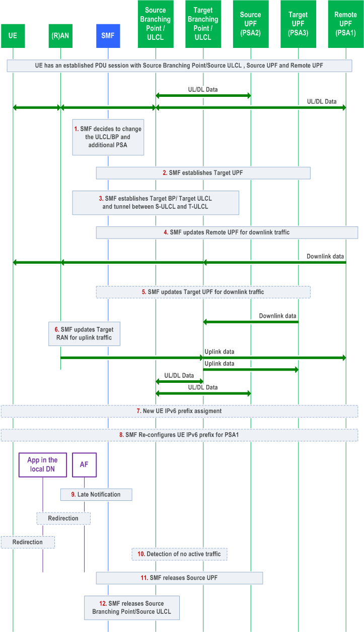
UE has an established PDU Session with a UPF including the PDU Session Anchor (Remote UPF). The PDU Session user plane involves at least the Source (R)AN, Source Branching Point or Source UL CL, local Source UPF (PSA2) and the Remote UPF (PDU Session Anchor, PSA1), where Source Branching Point or Source UL CL and PSA2 can be co-located.
Step 1.
At some point SMF decides to change the Branching Point or the UL CL due to UE mobility.
Step 2.
The SMF selects a local Target UPF (PSA3) and using N4 establishes the local Target UPF for the PDU Session.
In the case of IPv6 multi-homing PDU Session, a new IPv6 prefix corresponding to PSA3 is allocated (by the SMF or by the UPF depending on the deployment) and if the PCF has subscribed to the IP allocation/release event, the SMF performs the Session Management Policy Modification procedure as defined in clause 4.16.5 to provide the new allocated IPv6 prefix to the PCF.
The SMF may send an Early notification to the AF after PSA3 is selected. If the runtime coordination between 5GC and AF is enabled based on local configuration as specified in clause 4.3.6.3, according to the indication of "AF acknowledgment to be expected" included in AF subscription to SMF events, the SMF waits for a notification response from the AF before configuring the PSA3. If the SMF receives a negative notification response from the AF, the SMF may stop the procedure. This is defined in Figure 4.3.6.3-1.
Step 3.
The SMF selects a UPF and using N4 establishes the Target Branching Point or Target UL CL for the PDU Session. SMF provides the necessary uplink forwarding rules towards the PSA3 and PSA1 including the Tunnel Info for each UPF. If session continuity upon UL CL relocation is used, the SMF also uses N4 to establish an N9 forwarding tunnel between the Source UL CL and Target UL CL, including the Tunnel Info for each UPF. In addition, the AN Tunnel Info to target (R)AN is provided for downlink forwarding. In the case of UL CL, the SMF provides traffic filters indicating what traffic shall be forwarded towards PSA3, PSA1 and Source UL CL, respectively. In the case of IPv6 multi-homing, the SMF also provides traffic filters for the IPv6 prefixes corresponding to PSA3 and PSA1 indicating what traffic shall be forwarded towards PSA3 and PSA1 respectively. Target Branching Point or Target UL CL provides the CN Tunnel Info for downlink traffic.
Step 4.
The SMF updates the PSA1 via N4. It provides the PDU Session CN Tunnel Info for the downlink traffic.
Step 5.
The SMF updates the PSA3 via N4. It provides the CN Tunnel Info for downlink traffic. The SMF may also indicate PSA3 to buffer uplink data.
Step 6.
In the case of PDU session with UL CL, if the runtime coordination between 5GC and AF is enabled based on local configuration, according to the indication of "AF acknowledgment to be expected" included in AF subscription to SMF events, the SMF sends a late notification to the AF and waits for a notification response from the AF as described in step 9. If the SMF receives a negative notification response from the AF, the SMF may stop the procedure and remove the Target Branching Point or Target UL CL and PSA3. This is further defined in Figure 4.3.6.3-1.
The SMF updates (R)AN via N2 SM information over N11. It provides the new CN Tunnel Info corresponding to the Target Branching Point or the Target UL CL. If there is an existing UPF between the Target (R)AN and Target Branching Point or Target UL CL, the SMF updates the existing UPF via N4 instead of updating the (R)AN.
Step 7.
In the case of IPv6 multi-homing PDU Session, if the runtime coordination between 5GC and AF is enabled based on local configuration, according to the indication of "AF acknowledgment to be expected" included in AF subscription to SMF events, the SMF sends a late notification to the AF and waits for a notification response from the AF as described in step 9. If the SMF receives a negative notification response from the AF, the SMF may stop the procedure. This is further defined in Figure 4.3.6.3-1.
In the case of IPv6 multi-homing, the SMF notifies the UE of the availability of the new IP prefix @ PSA3. This is performed using an IPv6 Router Advertisement message (RFC 4861). Also, the SMF sends IPv6 multi-homed routing rule along with the IPv6 prefix to the UE using an IPv6 Router Advertisement message (RFC 4191) as described in clause 5.8.2.2.2 of TS 23.501.
Step 8.
In the case of IPv6 multi-homing, the SMF may re-configure the UE for the original IP prefix @ PSA1, i.e. SMF sends IPv6 multi-homed routing rule along with the IPv6 prefix to the UE using an IPv6 Router Advertisement message (RFC 4191) as described in clause 5.8.2.2.2 of TS 23.501.
Step 9.
The SMF sends a Late Notification to the AF indicating a change of DNAI as described in clause 4.3.6.3. In cases where target local DN is associated with another AF instance, SMF also sends notification to target AF as described in 4.3.6.3 and cancels any future notification message to source AF as it is no longer involved. The SMF may also indicate PSA3 to stop buffering and start forwarding uplink data based on the positive response for the Late Notification.
Step 10.
When session continuity upon UL CL relocation is used, detection of no active traffic over the N9 forwarding tunnel is performed during a time interval provisioned by SMF for User Plane inactivity report in order to release the N9 forwarding tunnel. The detection can be done by Source UL CL, which notifies the SMF of no active traffic over the N9 forwarding tunnel.
Step 11.
The SMF releases via N4 the PSA2.
Step 12.
The SMF releases the Source Branching Point or the Source UL CL.
4.3.5.8 Ethernet PDU Session Anchor Relocation |R16| p. 196
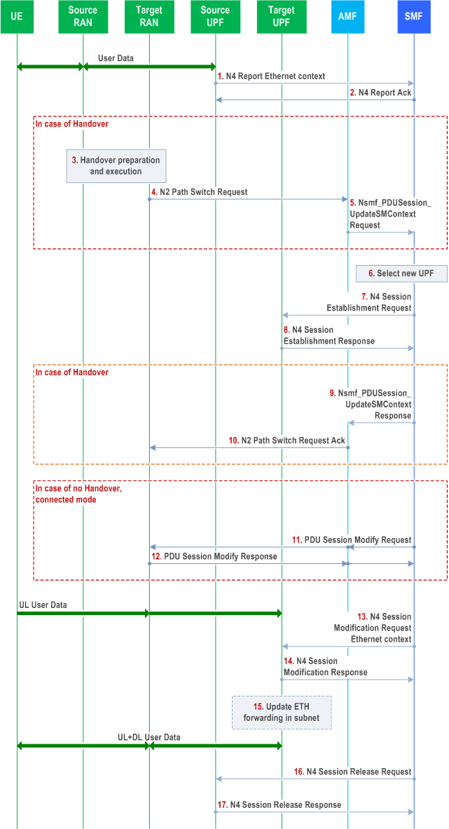
This procedure allows for Ethernet PDU Sessions to change the PDU Session Anchor (PSA) while the session remains set up. Originally the Ethernet PDU Session goes via the Source UPF acting as the PSA. The Ethernet context which contains all Ethernet specific information including the MAC address of the UE and possibly its VLAN tag(s) is reported from the Source PSA UPF to the SMF. It is possible to report multiple MAC addresses (with their VLAN tag(s)) if these are reachable via the UE.
The SMF determines whether and when a serving PDU Session anchor for an Ethernet PDU Session needs to be changed and selects the Target PSA UPF, establishes the N4 session at the Target PSA UPF. The information within the Ethernet context is sent to the Target UPF. Based on the information in the Ethernet context, the Target PSA UPF may take action to update the Ethernet forwarding in the data network.

Initially, the Ethernet PDU Session is established with the user data going via the Source UPF. The Source UPF acts as the PSA.
Step 1.
The Source UPF reports the Ethernet context which contains all Ethernet specific information including the MAC address of the UE and possibly its VLAN tag(s) that the UPF has learned from the UE side to the SMF. In the case of any changes in the Ethernet context, the change is updated to the SMF so that the SMF maintains an up-to-date state of the Ethernet context. This signalling is realized based on N4 reporting.
Step 2.
The UPF's report is acknowledged.
Step 3-5.
In the case of handover, the RAN handover preparation and execution is followed by path switch signalling to the AMF and corresponding signalling to SMF, as defined in clause 4.9.1.2.
Step 6.
The SMF decides that the PSA is to be changed for the Ethernet PDU Session and selects the Target UPF that will act as the new PSA. The decision may be triggered by a mobility event, such as receiving the message in step 5.
Step 7.
The Target UPF N4 session is established. The SMF provides the N3 tunnel endpoint used by RAN.
Step 8.
The establishment of the new N4 session is acknowledged from the Target UPF to the SMF. The UPF provides its N3 tunnel endpoint.
Step 9-10.
In the case of handover, the SMF signals to the RAN via the AMF to provide the Path Switch Request Ack, which includes the update of the uplink N3 tunnel endpoint to the target UPF. This signalling is defined in clause 4.9.1.2. In steps 9-10, an indication is sent from the SMF via the AMF to the RAN node indicating that the RAN node should not expect to receive an end marker packet. The RAN node may skip trying to reorder the downlink packets.
Step 11-12.
If there is no handover and the UE is in connected mode, the SMF sends PDU Session Modify Request message to the RAN via the AMF, which includes the update of the uplink N3 tunnel endpoint to the target UPF. The RAN acknowledges the message. The RAN node does not need to reorder the downlink packets.
After steps 9-10 or 11-12, uplink Ethernet frames pass via the target UPF. Downlink Ethernet frames may continue to be delivered from the source UPF to the RAN node. In the case of handover, the Ethernet frames are forwarded from the source RAN node to the target RAN node.
Step 13-14.
The SMF sends an N4 Session Modification Request to the Target UPF which includes the information in Ethernet context (i.e. MAC address and VLAN tag(s)) and a trigger for updating the Ethernet forwarding (next step). The Target UPF acknowledges by an N4 Session Modification Response.
Step 15.
The Target UPF may assist in the update of Ethernet forwarding tables of Ethernet switches in the DN via a variety of mechanisms, the use of which are specific to the DN and the specification of which are out-of-scope for 3GPP.
Step 16.
The N4 session is released at the Source UPF. The source UPF may wait for a configurable period before it stops delivering downlink Ethernet frames for the given PDU Session.
Step 17.
The N4 session release is acknowledged from the Source UPF to the SMF.