Content for TS 23.402 Word version: 18.3.0
0…
4…
4.2…
4.2.2
4.2.3
4.3…
4.4…
4.5…
4.5.7…
4.6…
4.7…
4.7.2…
4.8…
4.8.2a…
4.9…
5…
5.2…
5.4…
5.5
5.6…
5.7…
5.8…
6…
6.2…
6.3
6.4…
6.4.3…
6.5…
6.6…
6.7…
6.8…
6.10…
6.13…
6.15…
7…
7.2…
7.3
7.4…
7.5…
7.6…
7.8…
7.10…
8…
8.2.1.2
8.2.1.3…
8.2.2
8.2.3…
8.2.6…
8.3…
8.4…
8.5…
9…
9.3…
9.4…
10…
13…
16…
16.1.2…
16.1.6…
16.2…
16.2.1a…
16.3…
16.4…
16.7…
16.8…
16.10…
17…
A…
C…
E…
C Handover Flows Between Non-3GPP Accesses
C.1 General
C.2 Trusted Non-3GPP IP Access to Trusted Non-3GPP IP Access with DSMIPv6 over S2c Handover
C.3 Untrusted Non-3GPP IP Access with PMIPv6 to Trusted Non-3GPP IP Access with PMIPv6 Handover in the Non-Roaming Scenario
C.4 Trusted/Untrusted Non-3GPP IP Access with DSMIPv6 to Trusted Non-3GPP IP Access with PMIPv6 Handover in the Non-Roaming Scenario
C.5 Handover Between Two Untrusted Non-3GPP IP Accesses Connected to the Same ePDG
C.6 Handovers between APs of a Non-3GPP Trusted WLAN Access on S2a
C Handover Flows Between Non-3GPP Accesses p. 303
C.1 General p. 303
This clause describes non-exhaustive examples of flows for handover between non-3GPP accesses connected to the EPC. The handover scenarios are based on the mechanisms defined in clause 8 of this document.
C.2 Trusted Non-3GPP IP Access to Trusted Non-3GPP IP Access with DSMIPv6 over S2c Handover p. 303
In this scenario, the session starts in (source) trusted non3GPP access using DSMIPv6 over S2c. The session hands over to another (target) trusted non-3GPP access system. The UE subsequently initiates DSMIPv6 with the same PDN-GW to maintain the IP session.
In the non-roaming case, none of the optional entities in Figure C.2-1 are involved.
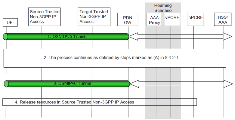
Figure C.2-1: Trusted non-3GPP to Trusted non-3GPP handover based on S2c
(⇒ copy of original 3GPP image)
(⇒ copy of original 3GPP image)
Step 1.
The UE uses a source Trusted non-3GPP IP access system. It has a local IP address from the non-3GPP system which is used as a care-of address in the DSMIPv6 registration to the PDN-GW. The UE maintains a security association with the PDN-GW.
Step 2.
The UE decides to initiate an access procedure with a new, target Trusted non-3GPP IP access. The procedure continues with the steps defined in Figure 8.6-1 (A)
Step 3.
The UE continues the ongoing session(s) via the same PDN-GW maintaining the same IP address.
Step 4.
Resources in the source Trusted Non-3GPP IP access are released.
C.3 Untrusted Non-3GPP IP Access with PMIPv6 to Trusted Non-3GPP IP Access with PMIPv6 Handover in the Non-Roaming Scenario p. 304
This clause shows a call flow for a handover when UE moves from an untrusted non-3GPP IP access network to the trusted non-3GPP access network. PMIPv6 is assumed to be used on S2a and S2b interfaces.
This procedure supports the non-roaming (Figure 4.2.2-1), home-routed roaming (Figure 4.2.3-1) and roaming with Local breakout (Figure 4.2.3-4) case. The PCRF in the HPLMN is informed of the change of access and any change in the policy that results is signalled to the Trusted non-3GPP IP Access. The signalling takes place through the vPCRF in the VPLMN. In the case of roaming with Local Breakout, the PDN-GW in the VPLMN exchanges messages with the vPCRF.
The optional interaction steps between the gateways and the PCRF in the above figure only occur if dynamic policy provisioning is deployed. Otherwise policy may be statically configured with the gateways.
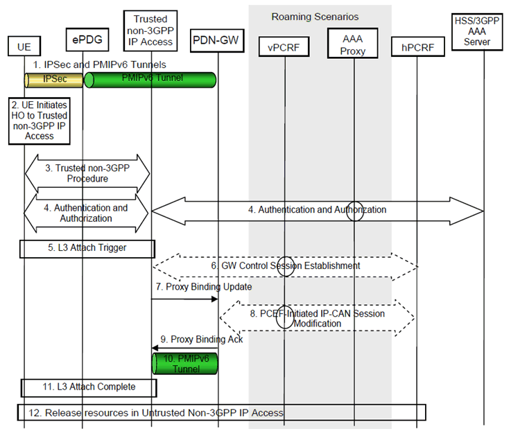
Step 1.
The UE is connected to the untrusted Non-3GPP IP Access. There is an IPsec tunnel between the UE and the ePDG and a PMIPv6 tunnel between the ePDG and the PDN-GW.
Step 2.
The UE moves to a Trusted Non-3GPP IP Access network.
Step 3.
The access specific procedures of the Trusted Non-3GPP IP Access are performed. These procedures are outside of the scope of 3GPP.
Step 4.
The EAP authentication procedure is initiated and performed involving the UE, Trusted Non-3GPP IP Access and the 3GPP AAA Server. In the roaming case, there may be several AAA proxies involved. As part of the authentication procedure, the information of the selected PDN-GW, e.g. PDN-GW's address, is conveyed to the MAG in the Trusted Non-3GPP IP Accesses.
Step 5.
After successful authentication and authorization, the L3 attach procedure is triggered.
Step 6.
The Trusted non-3GPP IP access initiates a Gateway Control Session Establishment Procedure with the PCRF as specified in TS 23.203 to obtain the rules required for the Trusted non-3GPP IP access to perform the bearer binding.
Step 7.
The MAG function in the Trusted Non-3GPP IP Access sends Proxy Binding Update message to the PDN-GW.
Step 8.
The PDN-GW executes a PCEF-Initiated IP-CAN Session Modification Procedure with the PCRF as specified in TS 23.203 to inform the PCRF of the new IP-CAN type and obtain the updates to the PCC rules.
Step 9.
The PDN-GW processes the proxy binding update and creates a binding cache entry for the UE. The PDN-GW allocates IP address for the UE. The PDN-GW then sends a Proxy Binding Acknowledgement to the MAG function in the Trusted Non-3GPP IP Access, including the IP address(s) allocated for the UE. The IP address allocated is same as that was assigned to UE before over the Untrusted Non-3GPP Accesses.
Step 10.
The PMIPv6 tunnel is set up between the Trusted Non-3GPP IP Access and the PDN-GW.
Step 11.
L3 attach procedure is completed. IP connectivity between the UE and the PDN-GW is set up for uplink and downlink direction over the trusted non-3GPP IP access.
Step 12.
The PDN-GW initiates resource allocation deactivation procedure in the untrusted non-3GPP IP access as defined in clause 6.12 or clause 7.9.
C.4 Trusted/Untrusted Non-3GPP IP Access with DSMIPv6 to Trusted Non-3GPP IP Access with PMIPv6 Handover in the Non-Roaming Scenario p. 305
This clause shows a call flow for a handover when UE moves from a source trusted/untrusted non-3GPP IP access network to a target trusted non-3GPP access network. PMIPv6 is assumed to be used on S2a and DSMIPv6 is assumed to be used on source trusted/untrusted access network.
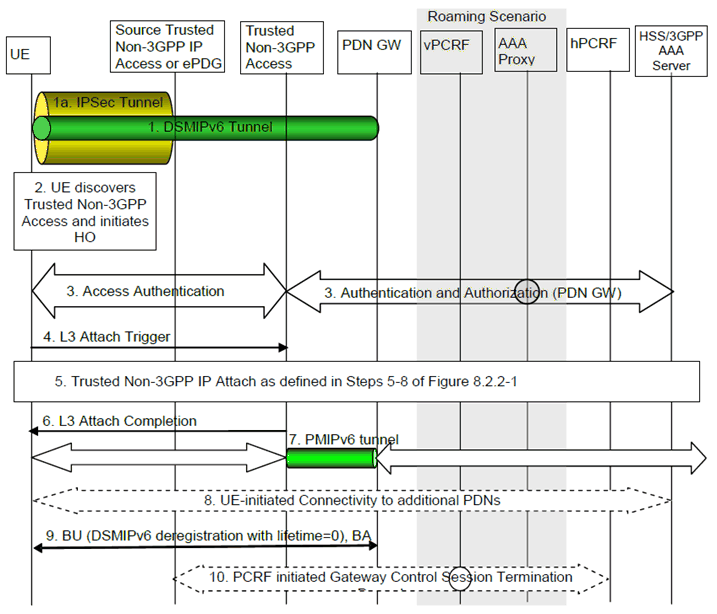
Figure C.4-1: S2c over trusted or untrusted Non-3GPP IP access to S2a (PMIPv6) Handover
(⇒ copy of original 3GPP image)
(⇒ copy of original 3GPP image)
This procedure supports the non-roaming (Figure 4.2.2-1), home routed roaming (Figure 4.2.3-1) and roaming with Local breakout (Figure 4.2.3-4) case. The PCRF in the HPLMN is informed of the change of access and any change in the policy that results is signalled to the Trusted non-3GPP IP Access. The signalling takes place through the vPCRF in the VPLMN. In the case of roaming with Local Breakout, the PDN-GW in the VPLMN exchanges messages with the vPCRF.
The optional interaction steps between the gateways and the PCRF in the above Figure only occur if dynamic policy provisioning is deployed. Otherwise policy may be statically configured with the gateways.
In case of connectivity to multiple PDNs, step 8 is repeated for each PDN the UE is connected to. This step can occur in parallel for each PDN. Other impacts related to the handover for multiple PDNs are described in clause 8.1. Alternatively, if supported by non-3GPP access technology and if the UE does not provide any APN upon handover attach in the trusted non-3GPP IP access, Step 5 is repeated for each PDN the UE is connected to, instead of Step 8. DSMIPv6 de-registration in step 9 will be performed for each PDN connection. These steps can occur in parallel for each PDN.
Step 1.
The UE is connected to the trusted/untrusted Non-3GPP Access using S2c.
Step 1a.
There is an IPsec tunnel between the UE and the ePDG if UE is connected over untrusted access network.
Step 2.
The UE moves to a Trusted Non-3GPP Access network.
Step 3.
The EAP authentication procedure is initiated and performed involving the UE, Trusted Non-3GPP IP Access and the 3GPP AAA Server. In the roaming case, there may be several AAA proxies involved. As part of the authentication procedure, the information of the selected PDN-GW, e.g. PDN-GW's address, is conveyed to the MAG in the Trusted Non-3GPP IP Accesses. The PDNs the UE is connected to are obtained from the HSS with the UE subscriber profile.
Step 4.
After successful authentication and authorization, the L3 attach procedure is triggered.
Step 5.
The UE continues the attach to the Trusted Non-3GPP IP Access as defined in Steps 5-8 of Figure 8.2.2-1, except that the IP-CAN session modification defined in step 7 is triggered as explained below.
Step 6.
L3 attach procedure is completed. IP connectivity between the UE and the PDN-GW is set for uplink and downlink direction over the trusted non-3GPP IP access.
Step 7.
The PMIPv6 tunnel is set up between the Trusted Non-3GPP IP Access and the PDN-GW. The UE can send/receive IP packets at this point.
Step 8.
In case of connectivity to multiple PDNs, the UE establishes connectivity to all the PDNs besides the Default PDN that the UE was connected to before the handover as described in clause 6.8.1.
Step 9.
The UE sends a BU (lifetime) to the PDN-GW to de-register its DSMIPv6 binding that was created while the UE was in non-3GPP access system. The PDN-GW responds with a BA message.
Any time after step 5, prior to receiving the de-registration Binding Update from the UE, the PDN-GW may de-register the DSMIPv6 binding. In this case the PDN-GW shall send a Binding Revocation Indication message to the UE.
Following the de-registration of the DSMIPv6 binding due to reception of de-registration Binding update or due to triggering Binding Revocation, the PDN-GW triggers PCEF initiated IP-CAN session modification, instead of doing it as part of the step 5.
Step 10.
The PCRF initiates "PCRF-initiated Gateway Control Session Termination" procedure to release the resources in the non-3GPP access. This procedure is triggered by the PCEF-Initiated IP-CAN Session Modification Procedure with the PCRF.
C.5 Handover Between Two Untrusted Non-3GPP IP Accesses Connected to the Same ePDG p. 307
This handover case is handled by MOBIKE, RFC 4555 [18], i.e. the existing IPSec tunnel, via the first untrusted non-3GPP IP access, is only modified for the use with the second untrusted non-3GPP access (and not torn down and re-created from scratch). It is assumed that the MOBIKE support indication has been sent by UE to ePDG in the initial attach.
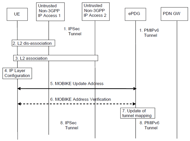
Figure C.5-1: Message flow for handover between two untrusted non-3GPP IP accesses based on MOBIKE
(⇒ copy of original 3GPP image)
(⇒ copy of original 3GPP image)
The following steps are performed:
Step 1.
For dual radio, step 2 is done after step 8.
The UE is connected via the IPSec tunnel to ePDG, from where a PMIPv6 tunnel is established to the PDN-GW. The UE is utilizing a local IP address (for previous IKEv2 signalling and outer IP header address).
Step 2.
The UE disconnects on L2 from untrusted non-3GPP IP access 1.
Step 3.
UE establishes L2 connectivity to untrusted non-3GPP IP access 2.
Step 4.
Configuration of a local IP address. (In case of dual radio multihoming capability with respect to the local IP address is required).
Step 5.
MOBIKE update address message exchange (in both directions, initiated by UE).
Step 6.
MOBIKE address verification, initiated by ePDG; this step is optional as per MOBIKE, RFC 4555 [18].
Step 7.
The tunnel mapping (between PMIPv6 tunnel and IPSec tunnel) is updated.
Step 8.
The modified IPSec tunnel is now in operation.
C.6 Handovers between APs of a Non-3GPP Trusted WLAN Access on S2a |R11| p. 308
No specific mechanisms are defined to support AP-to-AP handover with and without TWAG relocation. However, this does not preclude the support of IP address preservation in handovers without TWAG relocation when supported by procedures out of 3GPP scope.
D Void
![]()
![]()
![]()