Content for TS 23.402 Word version: 18.3.0
0…
4…
4.2…
4.2.2
4.2.3
4.3…
4.4…
4.5…
4.5.7…
4.6…
4.7…
4.7.2…
4.8…
4.8.2a…
4.9…
5…
5.2…
5.4…
5.5
5.6…
5.7…
5.8…
6…
6.2…
6.3
6.4…
6.4.3…
6.5…
6.6…
6.7…
6.8…
6.10…
6.13…
6.15…
7…
7.2…
7.3
7.4…
7.5…
7.6…
7.8…
7.10…
8…
8.2.1.2
8.2.1.3…
8.2.2
8.2.3…
8.2.6…
8.3…
8.4…
8.5…
9…
9.3…
9.4…
10…
13…
16…
16.1.2…
16.1.6…
16.2…
16.2.1a…
16.3…
16.4…
16.7…
16.8…
16.10…
17…
A…
C…
E…
8.5 Handover with Access Network Discovery and Selection
8.6 Handovers between non-3GPP IP access with GTP on S2b and 3GPP Access
8.6.1 Handover from Untrusted Non-3GPP IP Access with GTP on S2b to 3GPP Access
8.6.2 Handover from 3GPP access to untrusted Non-3GPP IP Access with GTP on S2b
...
...
8.5 Handover with Access Network Discovery and Selection p. 217
8.5.1 Handover between 3GPP Access and Trusted / Untrusted Non-3GPP IP Access with access network discovery and selection p. 217
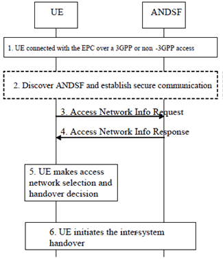
The Figure below shows the main steps involved in a handover between a 3GPP access and a non-3GPP IP access (also called an inter-system handover) when network discovery and selection information is provided by the network (see clause 4.8). This information is provided in order to control the UE's inter-system handover decisions and in order to reduce the battery consumption for inter-system mobility.

Figure 8.5.1-1: Handover between 3GPP Access and trusted / untrusted non-3GPP IP Access with Access Network Discovery and Selection
(⇒ copy of original 3GPP image)
(⇒ copy of original 3GPP image)
Step 1.
The UE is connected with a source access network (either a 3GPP access or a trusted / untrusted non-3GPP IP access). Its radio interfaces not connected to any access network may be in power saving or powered down mode.
Step 2.
If the inter-system mobility policies (see clause 4.8) in the UE indicate that inter-system mobility is allowed with at least one access technology type, then the UE may decide to discover neighbour access networks with assistance by the network. In this case, the UE discovers the address of ANDSF (if needed) as specified in clause 4.8, establishes secure communication with the ANDSF as specified in TS 33.402 and requests access network info from the ANDSF as specified in the steps below.
Step 3.
The UE sends an Access Network Info Request (UE Capabilities, UE Location) message to the H-ANDSF (in the non-roaming and roaming case) and the V-ANDSF (in the roaming case) to retrieve network discovery and selection information. The UE Capabilities indicate the capabilities of the UE pertaining to access network discovery, such as the access technology types that can be supported by the UE. If the UE Location is available in the UE, it should be included in the message to indicate the UE's current location, e.g. for the 3GPP access, Cell ID, TAI, and/or GPS (if available). If the UE Location is not included then other mechanisms may be used by ANDSF to identify the UE's current location.
Step 4.
The ANDSF responds with an Access Network Info Response (Available Access Network Info, Updated Inter-system Mobility Policies) message to the UE. The Available Access Networks Info contains a list of access networks that are available in the vicinity of UE. If the UE included one or more access technology types in the Access Network Info Request, then information about neighbour access network with the requested access technology types is included. The Updated Inter-system Mobility Policies may be included in order to update / install operator defined rules / preferences in the UE. These rules / preferences may indicate a preference value for an available access network and help the UE select an available access network that is more preferable to the current access network.
Step 5.
The UE powers up its appropriate radio interface(s) (if needed) and measures the available access networks for which inter-system mobility is allowed, as indicated by the updated / current inter-system mobility policies. The UE selects the most preferable available access network for inter-system mobility based on the inter-system mobility policies and user preferences.
Step 6.
If the UE selects a preferable access network for handover, then the UE initiates handover to the selected access network as described in clause 8.
8.6 Handovers between non-3GPP IP access with GTP on S2b and 3GPP Access |R10| p. 218
8.6.1 Handover from Untrusted Non-3GPP IP Access with GTP on S2b to 3GPP Access p. 218
8.6.1.1 General Procedure for GTP based S5/S8 for E-UTRAN Access p. 218
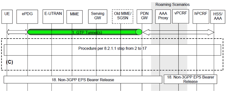
The steps involved in the handover from an untrusted non-3GPP IP access to E-UTRAN connected to EPC are depicted below for both the non-roaming and roaming cases and when GTP is used on S2b. It is assumed that while the UE is served by the untrusted non-3GPP IP access, GTP tunnel(s) are established between the ePDG and the PDN-GW in the EPC.

Figure 8.6.1.1-1: Handover from Untrusted Non-3GPP IP Access to E-UTRAN with GTP on S2b and GTP on S5/S8 interfaces
(⇒ copy of original 3GPP image)
(⇒ copy of original 3GPP image)
The home routed roaming (Figure 4.2.3-1), LBO (Figure 4.2.3-4) and non-roaming (Figure 4.2.2-1) scenarios are depicted in the Figure.
- In the LBO case, the vPCRF acts as an intermediary, sending the QoS Policy Rules Provision from the hPCRF in the HPLMN to the PDN-GW in the VPLMN. The vPCRF receives the Acknowledgment from the PDN-GW and forwards it to the hPCRF.
- In the non-roaming and home routed roaming case, the vPCRF is not involved.
Step 1.
The UE uses an untrusted non-3GPP access system and is being served by PDN-GW.
Step 2 to 17.
as for steps 2 to 17 of clause 8.2.1.1 with the following modifications:
Step 18.
For emergency sessions:
- On step 3, the UE sends an Attach Request to the MME with Request Type indicating "handover for emergency services". The message from the UE is routed by E-UTRAN to the MME as specified in TS 23.401 (E-UTRAN). The UE shall not include any APN.
- On step 4, the MME shall contact the HSS and attempt to authenticate the UE as described in TS 23.401.
- On step 5, if the UE has been successful authenticated, the MME may perform location update procedure and subscriber data retrieval from the HSS as specified in TS 23.401 by which the "PDN-GW currently in use for emergency services" is sent to the MME as part of the subscription information. Since the Request Type is "handover for emergency services", the "PDN-GW currently in use for emergency services" conveyed from the HSS to the MME will be stored in PDN subscription context. The MME receives information on all the PDNs the UE is connected to over the non-3GPP access in the Subscriber Data obtained from the HSS. If the UE has been authorized but not authenticated, Step 5 is skipped.
- On step 6, the MME selects the emergency APN, and a serving GW as described in TS 23.401. If the UE has been successfully authenticated and is non-roaming, and based on operator policy, the MME uses the "PDN-GW currently in use for emergency services" received from the HSS as anchor PDN-GW. Otherwise, e.g. if the UE has not been successfully authenticated, or the UE is roaming, or based on operator configuration (e.g. the network supports handovers to/from HRPD), the MME shall use the PDN-GW that is statically configured in the MME Emergency Configuration Data. The MME sends a Create Session Request (including IMSI, MME Context ID, PDN-GW address, Handover Indication, emergency APN) message to the selected Serving-GW. Since the Request Type is "handover for emergency services", a Handover Indication information is included.
- On step 9, the Charging Id provided by the PGW to the default and dedicated bearers in 3GPP access is the Charging Id previously assigned to the corresponding default and the dedicated bearers (i.e. bearer with the same QCI and ARP) of the PDN connection in the non-3GPP access on the S2b interface, although the Charging Id still applies to the non-3GPP access.
- On step 13, the Charging Id previously in use for the default and dedicated bearers in the non-3GPP access on the S2b interface now applies to the corresponding default and dedicated bearers in 3GPP access (i.e. bearer with the same QCI and ARP as in non-3GPP access).
The PDN-GW shall initiate resource allocation deactivation procedure in the untrusted non-3GPP IP access as defined in clause 7.9.2
For UEs and ePDGs supporting multiple IPsec SAs per PDN connection, i.e. one SA per the default bearer and per each S2b dedicated bearer, handover from untrusted non-3GPP to E-UTRAN shall result in the re-creation of all non-3GPP active bearers over E-UTRAN. The ePDG shall release the IKEv2 tunnel after handover is completed which shall implicitly remove the IPsec SAs.
8.6.1.2 General Procedure for GTP-based S5/S8 for UTRAN/GERAN p. 220
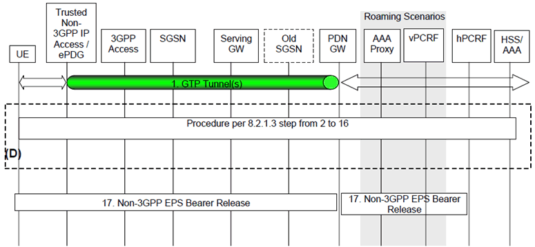
The steps involved in the handover from an untrusted non-3GPP IP access to UTRAN/GERAN connected to EPC are depicted below for both the non-roaming and roaming cases and when GTP is used on S2b. It is assumed that while the UE is served by the untrusted non-3GPP IP access, GTP tunnel(s) are established between the non-3GPP access network and the PDN-GW in the EPC.
The home routed roaming (Figure 4.2.3-1), LBO (Figure 4.2.3-4) and non-roaming (Figure 4.2.2-1) scenarios are depicted in the Figure.
- In the LBO case, the vPCRF acts as an intermediary, sending the QoS Policy Rules Provision from the hPCRF in the HPLMN to the PDN-GW in the VPLMN. The vPCRF receives the Acknowledgment from the PDN-GW and forwards it to the hPCRF.
- In the non-roaming and home routed roaming case, the vPCRF is not involved.

Figure 8.6.1.2-1: Handover from Untrusted Non-3GPP IP Access to UTRAN/GERAN with GTP on S2b and GTP on S5/S8 interfaces
(⇒ copy of original 3GPP image)
(⇒ copy of original 3GPP image)
In case of connectivity to multiple PDNs the same behaviour as described in clause 8.2.1.3 also applies to this procedure.
Step 1.
The UE uses an untrusted non-3GPP access system and is being served by PDN-GW.
Step 2) to 16.
As for steps 2 to 16 of clause 8.2.1.3.
On step 11, the Charging Id provided by the PGW to the default and dedicated bearers in 3GPP access is the Charging Id previously assigned to the corresponding default and the dedicated bearers (i.e. bearer with the same QCI and ARP) of the PDN connection in the non-3GPP access on the S2b interface, although the Charging Id still applies to the non-3GPP access.
On step 14, the Charging Id previously in use for the default and dedicated bearers in the non-3GPP access on the S2b interface now applies to the corresponding default and dedicated bearers in 3GPP access (i.e. bearer with the same value of QCI, ARP).
Step 17.
The PDN-GW shall initiate resource allocation deactivation procedure in the untrusted non-3GPP IP access as defined in clause 7.9.2.
For UEs and ePDGs supporting multiple IPsec SAs per PDN connection, i.e. one SA per S2b per the default bearer and per each dedicated bearer, handover from untrusted non-3GPP to UTRAN/GERAN shall result in the re-creation of all non-3GPP active bearers over UTRAN/GERAN. The ePDG shall release the IKEv2 tunnel after handover is completed which shall implicitly remove the IPsec SAs.
8.6.2 Handover from 3GPP access to untrusted Non-3GPP IP Access with GTP on S2b p. 222
8.6.2.1 3GPP Access to Untrusted Non-3GPP IP Access Handover with GTP on S2b p. 222
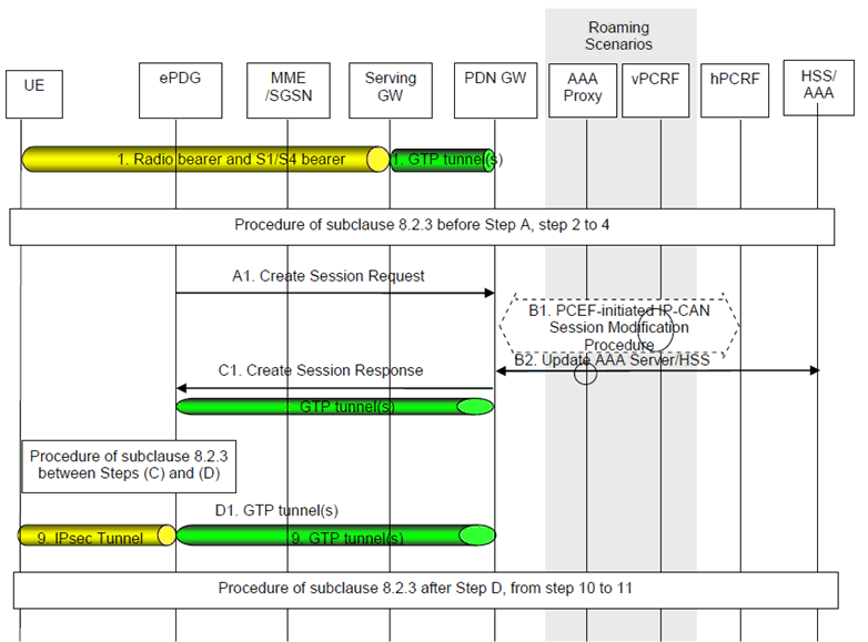
This clause shows a call flow for a handover when a UE moves from a 3GPP Access to an untrusted non-3GPP access network. GTP is assumed to be used on the S5/S8 interface and GTP is used on the S2b interface.

Figure 8.6.2.1-1: Handover from 3GPP Access to Untrusted Non-3GPP IP Access with GTP on S2b
(⇒ copy of original 3GPP image)
(⇒ copy of original 3GPP image)
The home routed roaming (Figure 4.2.3-1), LBO (Figure 4.2.3-4) and non-roaming (Figure 4.2.2-1) scenarios are depicted in the Figure.
- In the LBO case, the vPCRF acts as an intermediary, sending the QoS Policy Rules Provision from the hPCRF in the HPLMN to the PDN-GW in the VPLMN. The vPCRF receives the Acknowledgment from the PDN-GW and forwards it to the hPCRF.
- In the non-roaming and home routed roaming case, the vPCRF is not involved. In case of connectivity to multiple PDNs the same behaviour as described in clause 8.2.3 also applies to this procedure.
- On step 3, the UE attaches for emergency services as described in clause 7.2.5.
- On step 4, the IKEv2 tunnel establishment procedure is started by the UE. The ePDG IP address to which the UE needs to establish an IPsec tunnel is discovered as specified in clause 4.5.4a. During authentication and authorization, the HSS shall provide the AAA server with the "PDN-GW currently in use for emergency services", if available, as part of the subscription information, relayed by the AAA server to the ePDG.
- If the UE has been successfully authenticated, the UE is non-roaming and the UE included its IP address in step 3, and based on operator policy, the ePDG may select the "PDN-GW currently in use for emergency services" as anchor PDN-GW. Otherwise, e.g. if the UE has been authorized but not authenticated, or the UE is roaming, or based on operator configuration (e.g. the network supports handovers to/from HRPD), and the UE included its IP address in step 3, the ePDG shall select the PDN-GW that is statically configured in the ePDG Emergency Configuration Data.
Step A.1.
The ePDG sends a Create Session Request (IMSI, APN, Handover Indication, RAT type, ePDG TEID of the control plane, ePDG Address for the user plane, ePDG TEID of the user plane, EPS Bearer Identity, User Location Information) message to the PDN-GW. The RAT type indicates the non-3GPP IP access technology type. If the UE supports IP address preservation and included the address in step 3, the ePDG sets the 'Handover Indication' in the Creation Session Request to allow the PDN-GW to re-allocate the same IP address or prefix that was assigned to the UE while it was connected to the 3GPP IP access and to initiate a PCEF-Initiated IP-CAN Session Modification Procedure with the PCRF. For emergency sessions, the ePDG also includes the PDN-GW address obtained in step 4.
The User Location Information shall include UE local IP address and optionally UDP or TCP source port number (if NAT is detected). It may also include WLAN Location Information (and its Age) the ePDG may have received from the 3GPP AAA server about the UE.
Step B.1.
Step B.1 is the same as Step B of clause 8.2.3 with the following addition:
Step B.2.
- If requested by the PCRF, the PDN-GW forwards to the PCRF in the IP-CAN Session Establishment procedure following information extracted from User Location Information it may have received from the ePDG:
- The UE local IP address and optionally UDP or TCP source port number (if NAT is detected).
- WLAN location information in conjunction with the Age of this information.
The PDN-GW informs the 3GPP AAA Server of its PDN-GW identity and the APN corresponding to the UE's PDN Connection and obtains authorization information from the 3GPP AAA Server. The message includes information that identifies the PLMN in which the PDN-GW is located. The 3GPP AAA Server may update the information registered in the HSS as described in clause 12.
Step C.1.
The PDN-GW responds with a Create Session Response (PDN-GW Address for the user plane, PDN-GW TEID of the user plane, PDN-GW TEID of the control plane, PDN Type, PDN Address, EPS Bearer Identity, EPS Bearer QoS, APN-AMBR, Charging ID, Cause) message to the ePDG. The Create Session Response contains the IP address and/or the prefix that was assigned to the UE while it was connected to the 3GPP IP access. The Charging Id provided by the PGW is the Charging Id previously assigned to the default bearer of the PDN connection in the 3GPP access.
Depending upon the active PCC rules, the PDN-GW may create dedicated bearers on S2b interface. And in that case, it applies the Charging ID previously in use for the corresponding dedicated bearer(s) while the UE was connected to the 3GPP IP access (i.e. bearer with the same QCI and ARP as in 3GPP access).
Step D.1.
At the end of the handover procedure, the PDN connectivity service is provided by IPsec connectivity between the UE and the ePDG concatenated with S2b bearer(s) between the ePDG and the PDN-GW.
For UEs and ePDGs supporting multiple IPsec SAs per PDN connection, i.e. one SA per S2b per the default bearer and per each dedicated bearer, handover from E-UTRAN to untrusted non-3GPP shall result in the re-creation of all E-UTRAN active bearers over the untrusted non-3GPP access through the establishment of the needed dedicated bearers and IPsec SAs as described in clause 7.10.