Content for TS 23.402 Word version: 18.3.0
0…
4…
4.2…
4.2.2
4.2.3
4.3…
4.4…
4.5…
4.5.7…
4.6…
4.7…
4.7.2…
4.8…
4.8.2a…
4.9…
5…
5.2…
5.4…
5.5
5.6…
5.7…
5.8…
6…
6.2…
6.3
6.4…
6.4.3…
6.5…
6.6…
6.7…
6.8…
6.10…
6.13…
6.15…
7…
7.2…
7.3
7.4…
7.5…
7.6…
7.8…
7.10…
8…
8.2.1.2
8.2.1.3…
8.2.2
8.2.3…
8.2.6…
8.3…
8.4…
8.5…
9…
9.3…
9.4…
10…
13…
16…
16.1.2…
16.1.6…
16.2…
16.2.1a…
16.3…
16.4…
16.7…
16.8…
16.10…
17…
A…
C…
E…
5.4 Dedicated Bearer Procedures for E-UTRAN Access with PMIP-based S5/S8
5.4.1 General
5.4.2 Dedicated Bearer Activation
5.4.3 Bearer Modification with Bearer QoS Update
5.4.4 Dedicated Bearer Modification without Bearer QoS Update
5.4.5 Dedicated Bearer Deactivation
...
...
5.4 Dedicated Bearer Procedures for E-UTRAN Access with PMIP-based S5/S8 p. 93
5.4.1 General p. 93
The procedure given in Figure 5.4.1-1 applies to all dedicated resource allocation operations for E-UTRAN which are triggered by PCRF, with the only exception of MME-initiated Dedicated Bearer Deactivation procedure which is covered in clause 5.4.5.3 The procedures initiated by the S-GW in the E-UTRAN differ for each case.
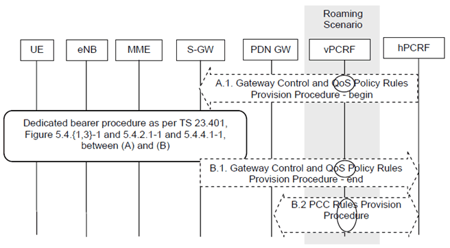
The procedure described in Figure 5.4.1-1 shows only the steps, due to PMIP based S5/S8, that are different from the GTP variant of the procedure given in TS 23.401.

Figure 5.4.1-1: Dedicated Resource Allocation Procedure, UE in Active Mode
(⇒ copy of original 3GPP image)
(⇒ copy of original 3GPP image)
This procedure applies to the Non-Roaming (Figure 4.2.1-1), Roaming (Figure 4.2.1-2) and Local Breakout (Figure 4.2.3-4) cases. For the Roaming and Local Breakout cases, the vPCRF forwards messages between the Serving-GW and the hPCRF. In the Local Breakout case, the vPCRF forwards messages between the PDN-GW and the hPCRF.
If dynamic policy provision is not deployed, the steps shown in the Figure are not taken. Instead, a configured static policy may be applied.
A.1)
Steps between A.1 and B.1 are described in clauses 5.4.1, 5.4.2.1, 5.4.3, 5.4.4.1 of TS 23.401.
The PCRF initiates the Gateway Control and QoS Rules Provision Procedure specified in TS 23.203 by sending a message with the QoS rules and Event Trigger information to the S-GW.
B.1)
Interactions between PCRF initiated dedicated bearer procedure and handover are described in clauses 5.7.1 and 5.7.2.
The Serving-GW indicates to the PCRF whether the requested QoS Policy Rules Provision could be enforced or not thus completing the GW Control and QoS Rules Provision procedure started in step A.1. The Serving-GW indicates User Location Information and/or UE Time Zone Information to the PCRF as an Event Report if the corresponding event trigger is set.
B.2)
5.4.2 Dedicated Bearer Activation p. 94
When the QoS Policy rules provided by the PCRF to the Serving Gateway in Step A.1 of Figure 5.4.1-1 above result in the Serving Gateway to decide to activate a dedicated bearer, this procedure is applied.
The procedure depicted in Figure 5.4.1-1 applies for this case. On receiving message A.1, the Serving-GW decides that a new bearer needs to be activated, the Serving-GW uses this QoS policy to assign the EPS Bearer QoS, i.e., it assigns the values to the bearer level QoS parameters (excluding AMBR); see clause 4.7.3 of TS 23.401. The Serving-GW follows the procedure shown in clause 5.4.1 of TS 23.401 by sending a Create Bearer Request message (EPS Bearer QoS, TFT, S1 TEID) to the MME.
The message descriptions for A.1, B.1 and B.2 in clause 5.4.1 apply to this case as well. The steps between A.1 and B.1 are described in clause 5.4.1 of TS 23.401.
5.4.3 Bearer Modification with Bearer QoS Update p. 94
5.4.3.1 PCC Initiated Bearer Modification with Bearer QoS Update p. 94
When the QoS Policy rules provided by the PCRF to the Serving Gateway in step A.1 of Figure 5.4.1-1 above results in the Serving Gateway to decide to modify the QoS of an already existing bearer, this procedure is applied. QoS modification may result in a bearer modification in the E-UTRAN access.
The procedure depicted in Figure 5.4.1-1 applies to this case as well. On receiving message A.1, the Serving-GW uses this QoS policy to determine that traffic flow(s) shall be aggregated to or removed from an active bearer. The Serving-GW generates the TFT and updates the EPS Bearer QoS to match the aggregated set of traffic flows. The Serving-GW then follows the procedure shown in clause 5.4.2 of TS 23.401 by sending the Update Bearer Request (EPS Bearer QoS, TFT) message to the MME.
The message descriptions for A.1, B.1 and B.2 in clause 5.4.1 apply to this procedure as well. The steps between A.1 and B.1 are described in clause 5.4.2.1 of TS 23.401.
5.4.3.2 HSS-Initiated Subscribed QoS Modification p. 94
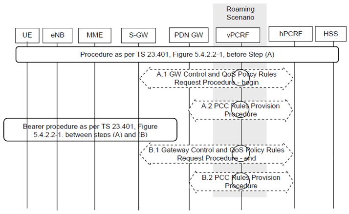
The HSS Initiated Subscribed QoS Modification for a PMIP-based S5/S8 is depicted in Figure 5.4.3.2-1.

A.1)
After Step A.1, the Serving-GW follows the procedure shown in clause 5.4.2.1 of TS 23.401 by sending the Update Bearer Request message to the MME. The procedure is completed when the Serving-GW receives a Update Bearer Response from the MME in Step 10 of clause 5.4.2.1 of TS 23.401.
The Serving-GW initiates the Gateway Control and QoS Policy Rules Request Procedure with the PCRF as specified in TS 23.203. The S-GW provides the updated default EPS Bearer QoS for the default bearer to the PCRF and the PCRF responds with updated QoS rules. The PCRF makes a PCC decision as a result of the Gateway Control and QoS policy request and provides the updated QoS Rules to the Serving-GW.
A.2)
The PCRF initiates the PCC Rules Provision Procedure with the PDN-GW as specified in TS 23.203 to updates the rules in the PDN-GW.
B.1)
The Serving-GW indicates to the PCRF whether the requested QoS Policy Rules Provision could be enforced or not and thus completing the GW Control and QoS Rules Provision procedure started in step A.1.
B.2)
The PCRF executes the Policy and Charging Rules Provision Procedure as specified in TS 23.203 to update the PCC rules in the PDN-GW.
5.4.4 Dedicated Bearer Modification without Bearer QoS Update p. 95
When the QoS Policy rules provided by the PCRF to the Serving Gateway in step A.1 of Figure 5.4.1-1 above results in the Serving Gateway to decide to only update the set of TFTs corresponding to an already existing dedicated bearer, this procedure is applied.
The procedure depicted in Figure 5.4.1-1 applies to this case as well. On receiving message A.1, the Serving-GW uses this QoS policy to determine that traffic flow(s) shall be aggregated to or removed from an active dedicated bearer. The Serving-GW generates the TFT and determines that no update of the EPS Bearer QoS is needed. The Serving-GW then follows the procedure shown in clause 5.4.3 of TS 23.401 by sending the Update Bearer Request (TFT) message to the MME.
The message descriptions for A.1, B.1 and B.2 in clause 5.4.1 apply to this procedure as well. The steps between A.1 and B.1 are described in clause 5.4.3 of TS 23.401.
5.4.5 Dedicated Bearer Deactivation p. 96
5.4.5.1 PCC-initiated Dedicated Bearer Deactivation p. 96
When the QoS Policy rules provided by the PCRF to the Serving Gateway in step A.1 of Figure 5.4.1-1 above results in the Serving Gateway to decide to deactivate an existing dedicated bearer, this procedure is applied.
The procedure depicted in Figure 5.4.1-1 applies to this case as well. On receiving message A.1, the Serving-GW uses this QoS policy to determine that a dedicated bearer needs to be deactivated, the Serving-GW follows the procedure shown in clause 5.4.4 of TS 23.401 by sending the Delete Bearer Request message to the MME. If the S-GW determines that the default bearer needs to be deactivated, the S-GW follows the procedure specified in clause 5.6.2.1.
The message descriptions for A.1, B.1 and B.2 in clause 5.4.1 apply to this procedure as well. The steps between A.1 and B.1 are described in clause 5.4.4.1 of TS 23.401.
5.4.5.2 Void
5.4.5.3 MME-initiated Dedicated Bearer Deactivation p. 96
This clause contains the procedure steps that vary between the GTP and PMIP variant of S5 and S8 for the procedure defined in clause 5.4.4.2 of TS 23.401 for -MME initiated dedicated bearer deactivation.

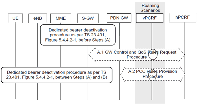
This procedure applies to the Non-Roaming (Figure 4.2.1-1), Roaming (Figure 4.2.1-2) and Local Breakout (Figure 4.2.3-4) cases. For the Roaming and Local Breakout cases, the vPCRF forwards messages between the Serving-GW and the hPCRF. In the Local Breakout case, the vPCRF forwards messages between the PDN-GW and the hPCRF.
The optional interaction steps between the gateways and the PCRF in the procedures in Figure 5.4.5.3-1 only occur if dynamic policy provisioning is deployed. Otherwise policy may be statically configured with the gateway.
Before Step A.1, the procedure shown in clause 5.4.4.2 of TS 23.401 is followed and the Serving-GW receives a Delete Bearer Command message from the MME.
Step A.1.
The Serving-GW decides to deactivate the bearers and initiates the Gateway Control and QoS Policy Rules Request Procedure with the PCRF as specified in TS 23.203. The Serving-GW informs the PCRF about the deleted QoS Rules and indicates User Location Information and/or UE Time Zone Information to the PCRF as an Event Report if the corresponding event trigger is set.
Step A.2.
The PCRF initiates the PCC Rules Provision Procedure with the PDN-GW as specified in TS 23.203 to updates the rules in the PDN-GW. The PCC rules provide the PDN-GW with information required to enforce the remaining dedicated resource allocation policy, after removing PCC rules corresponding to the QoS rules deactivated by step A.1.
After step A.1, the Serving-GW follows the procedure shown in clause 5.4.4.2 of TS 23.401 by sending the Delete Bearer Request message to the MME. The Serving-GW does not need to wait for step A.1 to complete to proceed with the deactivation of bearers with the MME. The procedure is completed when the Serving-GW receives a Delete Bearer Response from the MME in Step 8 of clause 5.4.4.2 of TS 23.401.