Content for TS 23.402 Word version: 18.3.0
0…
4…
4.2…
4.2.2
4.2.3
4.3…
4.4…
4.5…
4.5.7…
4.6…
4.7…
4.7.2…
4.8…
4.8.2a…
4.9…
5…
5.2…
5.4…
5.5
5.6…
5.7…
5.8…
6…
6.2…
6.3
6.4…
6.4.3…
6.5…
6.6…
6.7…
6.8…
6.10…
6.13…
6.15…
7…
7.2…
7.3
7.4…
7.5…
7.6…
7.8…
7.10…
8…
8.2.1.2
8.2.1.3…
8.2.2
8.2.3…
8.2.6…
8.3…
8.4…
8.5…
9…
9.3…
9.4…
10…
13…
16…
16.1.2…
16.1.6…
16.2…
16.2.1a…
16.3…
16.4…
16.7…
16.8…
16.10…
17…
A…
C…
E…
7.8 S2c Bootstrapping via DSMIPv6 Home Link over an Un-Trusted Access
7.9 PDN-GW initiated Resource Allocation Deactivation
7.9.1 PDN-GW initiated Resource Allocation Deactivation with PMIPv6 on S2b
7.9.2 PDN-GW initiated Resource Allocation Deactivation with GTP on S2b
...
...
7.8 S2c Bootstrapping via DSMIPv6 Home Link over an Un-Trusted Access p. 179
When the UE is connected on an un-trusted non-3GPP access considered to be DSMIPv6 home link for the UE based on clause 4.5.6, the UE may trigger the establishment of S2c IKEv2 SA, e.g. to optimize future handovers to other accesses using S2c. For each PDN connection, the S2c IKEv2 SA establishment has to be performed separately.
Once the UE is attached to the PDN over the un-trusted non-3GPP access, the procedure describing the bootstrapping is in clause 15.1.
7.9 PDN-GW initiated Resource Allocation Deactivation p. 179
7.9.1 PDN-GW initiated Resource Allocation Deactivation with PMIPv6 on S2b |R10| p. 179
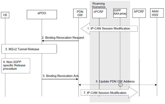
This procedure is performed to release all the resources associated with the PDN address, for example, due to IP-CAN session modification requests from the PCRF or due to handover Non-3GPP to 3GPP. When it is performed for an handover, the connections associated with the PDN address are released, but the PDN address is kept in the PDN-GW.

Figure 7.9-1: PDN-GW Initiated Resource Allocation Deactivation with PMIPv6 on S2b
(⇒ copy of original 3GPP image)
(⇒ copy of original 3GPP image)
The PDN-GW initiated resource allocation deactivation procedure for S2b PMIP reference point is defined in the following.
Step 1.
If dynamic PCC is deployed, the PDN-GW initiated Resource Allocation Deactivation procedure may for example be triggered due to 'IP-CAN session Modification procedure', as defined in TS 23.203. In this case, the resources associated with the PDN connection in the PDN-GW are released.
The PDN-GW initiated Resource Allocation Deactivation can also be triggered during handovers from Non-3GPP to 3GPP.
Step 2.
The PDN-GW sends a Binding Revocation Indication message to the trusted non-3GPP IP access.
Step 3.
The IKEv2 tunnel release is triggered from the ePDG if all bearers belonging to the PDN connection are released.
Step 4.
The resources may be released in the non-3GPP IP access.
Step 5.
The ePDG send a Buinding Revocation Acknowledgement message to the PDN-GW.
Step 6.
In the case where the resources corresponding to the PDN connection are released in PDN-GW, the PDN-GW informs the 3GPP AAA Server of the PDN disconnection. If the UE no longer has any context in the 3GPP AAA Server, the 3GPP AAA Server notifies the HSS as described in clause 12.1.2.
Step 7.
The PDN-GW indicates to the PCRF whether the requested PCC decision was successfully enforced by completing the PCRF-initiated IP-CAN Session Modification procedure or the PCEF initiated IP-CAN Session Modification procedure as defined in TS 23.203, proceeding after the completion of IP-CAN bearer signalling.
7.9.2 PDN-GW initiated Resource Allocation Deactivation with GTP on S2b |R10| p. 180
This procedure can be used to deactivate a dedicated bearer or deactivate all bearers belonging to a PDN address, for example, due to IP-CAN session modification requests from the PCRF or due to handover from Non-3GPP to 3GPP access. If the default bearer belonging to a PDN connection is deactivated, the PDN-GW deactivates all bearers belonging to the PDN connection.
When it is performed for a handover, the connections associated with the PDN address are released, but the PDN address is kept in the PDN-GW.

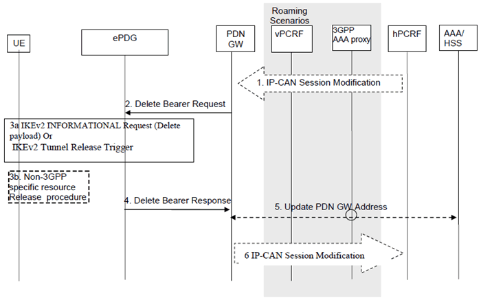
Figure 7.9.2-1: PDN-GW Initiated Bearer Deactivation with GTP on S2b
(⇒ copy of original 3GPP image)
(⇒ copy of original 3GPP image)
This procedure applies to the Non-Roaming (Figure 4.2.2-1), Roaming (Figure 4.2.3-1) and Local Breakout (Figure 4.2.3-4) cases. In the Local Breakout case, the vPCRF forwards messages between the PDN-GW and the hPCRF. In the non-roaming and home routed roaming cases, the vPCRF is not involved at all.
The optional interaction steps between the PDN-GW and the PCRF in the procedures in Figure 7.9.2-1 only occur if dynamic policy provisioning is deployed. Otherwise policy may be statically configured within the PDN-GW.
Step 1.
If dynamic PCC is deployed, the PDN-GW initiated Bearer Deactivation procedure may for example be triggered due to 'IP-CAN session Modification procedure', as defined in TS 23.203. In this case, the resources associated with the PDN connection in the PDN-GW are released. The PCRF may also include a request to provide the User Location Info to the PDN-GW.
The PDN-GW initiated Resource Allocation Deactivation can also be triggered during handovers from Non-3GPP to 3GPP.
Step 2.
The PDN-GW sends a Delete Bearer Request message (EPS Bearer Identity or Linked EPS Bearer Identity, Cause) to the ePDG. The Linked EPS Bearer Identity shall be present and set to the identity of the default bearer associated with the PDN connection if the PDN-GW requests to release all the bearers of the PDN connection. Otherwise, the EPS Bearer Identity shall be present and set to the identity of the dedicated S2b bearer(s) to release if the PDN-GW requests to deactivate dedicated S2b bearer(s).
Step 3a only applies if both the UE, and the ePDG support a separate IPsec Security associations per dedicated S2b bearer.
Step 3a.
If the PDN connection has multiple active S2b bearers, and the ePDG maintained a binding with a IPsec SA for the S2b bearer that is being released, then it shall use the IKEv2 INFORMATIONAL exchange with Delete Payloads, as defined in RFC 7296, to remove the IPsec SA between ePDG and UE over SWu for the deactivated S2b bearer. Otherwise, the IKEv2 tunnel release is triggered from the ePDG if all bearers belonging to the PDN connection are released.
Step 3b.
The resources may be released in the non-3GPP IP access according to the conditions in step 3a.
Step 4.
The ePDG deletes the bearer contexts related to the Delete Bearer Request, and acknowledges the bearer deactivation to the PDN-GW by sending a Delete Bearer Response (EPS Bearer Identity, User Location Information) message.
The User Location Information shall include UE local IP address and optionally UDP or TCP source port number (if NAT is detected). It may also include WLAN Location Information (and its Age) the ePDG may have received from the 3GPP AAA server about the UE. When the PDN-GW receives no WLAN Location Information from the ePDG it shall delete any such information it may have stored for the PDN connection.
Step 5.
In the case where the resources corresponding to the PDN connection are released in PDN-GW, the PDN-GW informs the 3GPP AAA Server of the PDN disconnection. If the UE no longer has any context in the 3GPP AAA Server, the 3GPP AAA Server notifies the HSS as described in clause 12.1.2.
Step 6.
The PDN-GW deletes the bearer context related to the deactivated EPS bearer. If the dedicated bearer deactivation procedure was triggered by receiving a PCC decision message from the PCRF, the PDN-GW indicates to the PCRF whether the requested PCC decision was successfully enforced by completing the PCRF-initiated IP-CAN Session Modification procedure or the PCEF initiated IP-CAN Session Modification procedure as defined in TS 23.203, proceeding after the completion of IP-CAN bearer signalling. If requested by the PCRF, the PDN-GW forwards to the PCRF following information extracted from User Location Information it may have received from the ePDG:
- WLAN location information in conjunction with the Age of this information,
- The UE local IP address and optionally UDP or TCP source port number (if NAT is detected).