Content for TS 23.402 Word version: 18.3.0
0…
4…
4.2…
4.2.2
4.2.3
4.3…
4.4…
4.5…
4.5.7…
4.6…
4.7…
4.7.2…
4.8…
4.8.2a…
4.9…
5…
5.2…
5.4…
5.5
5.6…
5.7…
5.8…
6…
6.2…
6.3
6.4…
6.4.3…
6.5…
6.6…
6.7…
6.8…
6.10…
6.13…
6.15…
7…
7.2…
7.3
7.4…
7.5…
7.6…
7.8…
7.10…
8…
8.2.1.2
8.2.1.3…
8.2.2
8.2.3…
8.2.6…
8.3…
8.4…
8.5…
9…
9.3…
9.4…
10…
13…
16…
16.1.2…
16.1.6…
16.2…
16.2.1a…
16.3…
16.4…
16.7…
16.8…
16.10…
17…
A…
C…
E…
16.8 UE Initiated PDN connectivity request procedure in WLAN on S2a for Multi-connection Mode
16.8.1 Supporting GTP S2a
16.8.2 Supporting PMIP S2a
16.9 UE/TWAN Initiated PDN disconnection for Multi-connection Mode
16.9.1 Supporting GTP S2a
16.9.2 Supporting PMIP S2a
...
...
16.8 UE Initiated PDN connectivity request procedure in WLAN on S2a for Multi-connection Mode |R12| p. 285
16.8.1 Supporting GTP S2a p. 285
When the UE is connected to a trusted WLAN and the multi-connection mode has been selected (as described in clause 16.2.1), the UE may use the PDN connectivity request procedure specified below in order to establish a PDN connection over the connected WLAN. This procedure is also used to request for connectivity to an additional PDN over a trusted WLAN with GTP on S2a when the UE is simultaneously connected to E-UTRAN and a trusted WLAN, and the UE already has active PDN connections over both the accesses.
There can be more than one PDN connection per APN when GTP is used between the TWAN and the PDN-GW. During the establishment of a new PDN connection, the TWAN allocates and sends a default EPS bearer ID to the PDN-GW. The default EPS bearer ID is unique in the scope of the UE within a TWAG, i.e. the IMSI and the default EPS bearer ID togther identify a PDN connection within a TWAG. In order to be able to identify a specific established PDN connection, both the TWAG and the PDN-GW shall store the default EPS bearer ID.
An UE attached for emergency services shall not initiate any additional PDN Connectivity Request procedure. An UE attached for regular services may request a PDN connection for emergency services if an emergency PDN connection is not already active.
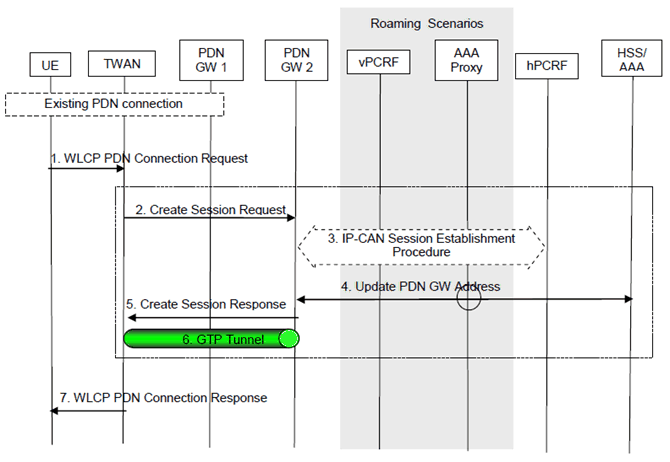
Figure 16.8.1-1: UE-Initiated Connectivity to PDN in WLAN on GTP S2a
(⇒ copy of original 3GPP image)
(⇒ copy of original 3GPP image)
This procedure applies to the Non-Roaming, Home Routed Roaming and Local Breakout cases. In the Local Breakout case, the vPCRF forwards messages between the PDN-GW and the hPCRF. In the Home Routed Roaming and LBO cases, the 3GPP AAA Proxy serves as an intermediary between the Trusted Non-3GPP IP Access and the 3GPP AAA Server in the HPLMN. In the non-roaming and Home Routed Roaming case, the vPCRF is not involved at all.
If dynamic policy provisioning is not deployed, the optional steps of interaction between the PDN-GW and PCRF do not occur.
Step 1.
In the case of a PDN connection for emergency services:
The UE sends a WLCP PDN Connection Request (APN, PDN Type, Protocol Configuration Options, Request Type, Multiple Bearer Capability Indicator) to the TWAN. The UE sends the WLCP PDN Connection Request to the control plane address of TWAN it received during EAP authentication and authorization procedure as described in clause 16.2.1. The Request Type indicates "initial request" when the UE requests new PDN connection over the WLAN access network. The UE may indicate the requested APN. If the UE does not indicate an APN, then the default APN will be used in the following steps. The Protocol Configuration Options (PCO) may be sent to transfer parameters to the PDN-GW, and is sent transparently through the TWAN. The Multiple Bearer Capability Indicator indicates if UE supports multiple WLCP bearers per PDN connection.
Step 2-6.
Step 2 to Step 6 are described as Step 3 to Step 7 in clause 16.2.1.
Step 7.
The TWAN returns a WLCP PDN Connection Response (APN, PDN Type, PDN Address, PDN Connection ID, User Plane Connection ID, Protocol Configuration Options) message to the UE to acknowledge the establishment of a new point-to-point link between the UE and the TWAG. The User Plane Connection ID is the per-UE unique MAC address of the TWAN which is used by the UE and the TWAN for encapsulating user plane packets for the default bearer of this PDN connection. If the Multiple Bearer Capability Indicator is not set in step 1 or if the TWAG does not support multiple WLCP bearers per PDN connection, the provided MAC address will be used for all traffic of this PDN connection. If the UE did not indicate the APN in the WLCP PDN Connection Request, then the response indicates the APN selected by the network (e.g. the default APN). The PDN Connection ID is stored in the TWAN to associate the established point-to-point link between the UE and TWAG with all the S2a bearers for this PDN connection. The PDN Connection ID is sent to and stored in the UE to identify this new established PDN connection. The UE will use this PDN Connection ID in subsequent procedures, such as PDN disconnection procedure.
If the IPv6 prefix is allocated, a Router Advertisement with the IPv6 prefix is sent to the UE after step 7. The UE may perform additional IP layer configuration as per standard IETF procedures, e.g. IPv6 Stateless Address Autoconfiguration according to RFC 4862, and Stateless DHCPv6 according to RFC 3736.
- if the TWAN supports emergency services and is located in the same country as the UE, the above procedure takes place with following exceptions:
- The UE adds an emergency request indication in the WLCP PDN Connection Request sent to the TWAG;
- When the WLCP PDN Connection Request contains an emergency request indication, the TWAG ignores any APN received from the UE in that message, considers that the target APN is the APN configured within its Emergency Configuration Data and does not check whether this APN is part of the subscription of the UE;
- Step 5 applies with the following addition: When informing the 3GPP AAA Server of the PDN-GW identity, the selected PDN-GW also indicates that the PDN-GW is used for emergency services. The AAA server then sends the "PDN-GW currently in use for emergency services", which comprises the PDN-GW address and an indication that the PDN connection is for emergency services to the HSS.
- if the TWAN does not support emergency services or is not located in the same country as the UE, the UE shall detach from the TWAN in order to attach to another TWAN that supports emergency services.
16.8.2 Supporting PMIP S2a p. 287
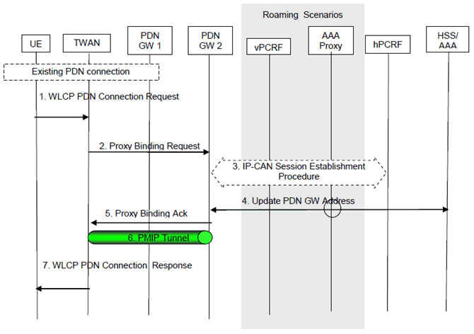
Figure 16.8.2-1: UE-Initiated Connectivity to PDN in WLAN on PMIP S2a
(⇒ copy of original 3GPP image)
(⇒ copy of original 3GPP image)
When the UE is connected to a trusted WLAN and the multi-connection mode has been selected (as described in clause 16.2.2), the UE may use the PDN connectivity request procedure in order to establish a PDN connection over the connected WLAN. This procedure is also used to request for connectivity to an additional PDN over a trusted WLAN with PMIPv6 on S2a when the UE is simultaneously connected to E-UTRAN and a trusted WLAN, and the UE already has active PDN connections over both the accesses.
The procedure is similar to GTP based S2a call flows in clause 16.8.1 with the following differences:
- Step 2 is a Proxy Binding Update as described in Step 3 in clause 16.2.2.
- Step 5 is a Proxy Binding Acknowledgement as described in Step 6 in clause 16.2.2.
16.9 UE/TWAN Initiated PDN disconnection for Multi-connection Mode |R12| p. 288
16.9.1 Supporting GTP S2a p. 288
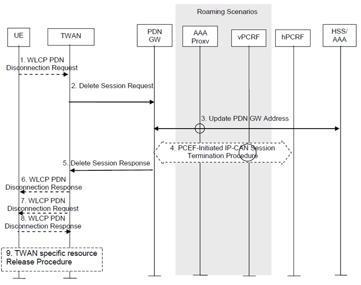
Figure 16.9.1-1: UE/TWAN requested PDN disconnection procedure in WLAN on GTP S2a for Multi-Connection Mode
(⇒ copy of original 3GPP image)
(⇒ copy of original 3GPP image)
This procedure applies to the Non-Roaming, Roaming with home routed and romaing with local breakout. In the Local Breakout case, the vPCRF forwards messages between the PDN-GW and the hPCRF. In the LBO cases, the 3GPP AAA Proxy serves as an intermediary between the Trusted WLAN Access and the 3GPP AAA Server in the HPLMN. In the non-roaming and Home Routed Roaming case, the vPCRF is not involved at all.
If dynamic policy provisioning is not deployed, the optional steps of interaction between the PDN-GW and PCRF do not occur.
Step 1.
If the PDN disconnection is initiated by the UE, the UE sends a WLCP PDN Disconnection Request containing a PDN Connection ID to the TWAG.
Step 2-5.
Steps 2-5 are the same as steps 2-5 in clause 16.3.1.1.
Step 6.
If the PDN disconnection was initiated by the UE in step 1, then the UE is informed of the disconnection by means of a WLCP PDN Disconnection Response.
Step 7.
If the PDN disconnection was initiated by the TWAG, then the UE is informed of the disconnection by means of a WLCP PDN Disconnection Request containing the PDN Connection ID.
Step 8.
The UE acknowledges the disconnection request received in step 7.
Step 9.
The TWAN specific reousces belonging to the PDN connection are released with a method which is out of 3GPP scope.
16.9.2 Supporting PMIP S2a p. 289
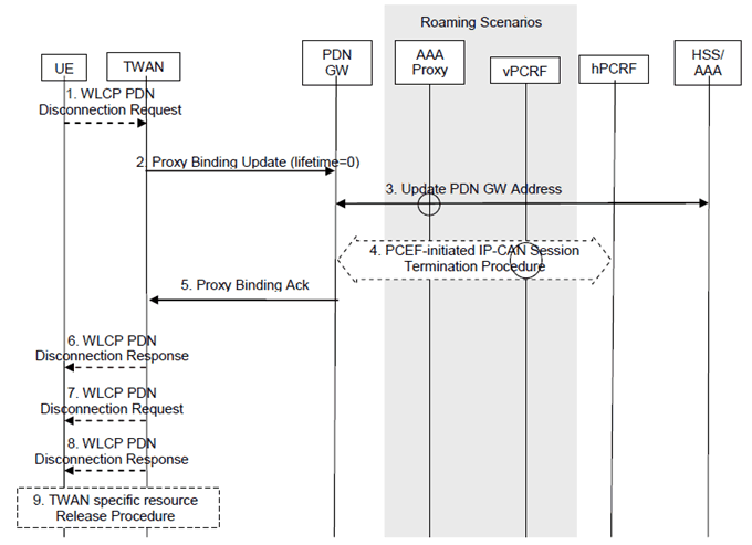
Figure 16.9.2-1: UE/TWAN requested PDN disconnection in WLAN on PMIP S2a for Multi-connection Mode
(⇒ copy of original 3GPP image)
(⇒ copy of original 3GPP image)
The procedure is similar to GTP based S2a call flows in clause 16.9.1 with the following differences:
- Step 2 is a Proxy Binding Update (lifetime=0) for the PDN connection to be deleted sent by TWAN to the PDN-GW. The details of the Proxy Binding Update message are described in step3 in clause 6.4.1.1. Additionally, the Proxy Binding Update includes the current TWAN Identifier as described in clause 16.1.7, the Timestamp of this TWAN-Identifier and the UE Time Zone.
- Step 5 is a Proxy Binding Acknowledgement sent by the PDN-GW to TWAN. The details of the Proxy Binding Acknowledgement message are described in step6 in clause 6.4.1.1.
![]()
![]()
![]()