Content for TS 23.402 Word version: 18.3.0
0…
4…
4.2…
4.2.2
4.2.3
4.3…
4.4…
4.5…
4.5.7…
4.6…
4.7…
4.7.2…
4.8…
4.8.2a…
4.9…
5…
5.2…
5.4…
5.5
5.6…
5.7…
5.8…
6…
6.2…
6.3
6.4…
6.4.3…
6.5…
6.6…
6.7…
6.8…
6.10…
6.13…
6.15…
7…
7.2…
7.3
7.4…
7.5…
7.6…
7.8…
7.10…
8…
8.2.1.2
8.2.1.3…
8.2.2
8.2.3…
8.2.6…
8.3…
8.4…
8.5…
9…
9.3…
9.4…
10…
13…
16…
16.1.2…
16.1.6…
16.2…
16.2.1a…
16.3…
16.4…
16.7…
16.8…
16.10…
17…
A…
C…
E…
16.1.2 High level functions
16.1.3 Reference points
16.1.4 Protocol Stacks
16.1.4A Control Plane
16.1.4B User plane
16.1.5 IP address allocation
...
...
16.1.2 High level functions p. 249
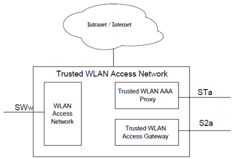
The detailed functional split within a Trusted WLAN Access Network (TWAN) is not in the scope of 3GPP. Nevertheless, the procedures specified in the subsequent sections assume the following functions in the TWAN:
- A WLAN Access Network (WLAN AN). WLAN AN includes a collection of one or more WLAN access points. An access point terminates the UE's WLAN IEEE 802.11 link defined in IEEE Std 802.11-2012 [64].
-
A Trusted WLAN Access Gateway (TWAG). This function terminates S2a.
- When the TWAN provides access to EPC in Transparent Single-Connection mode or in Single-Connection mode, it forwards packets between the UE-TWAG point-to-point link and the S2a tunnel for that UE. The association in the TWAN between UE-TWAG point-to-point link and S2a tunnel is based on the UE MAC address.
- When the TWAN provides access to EPC in Multi-Connection mode, it forwards user plane packets between the UE-TWAG point-to-point link corresponding to a specific WLCP bearerand the associated S2a tunnel for that UE. The UE's MAC address and a TWAG's MAC address that is assigned for a specific WLCP bearer are used to identify the point-to-point link between the UE and its serving TWAG, which corresponds to the S2a tunnel for the associated WLCP bearer.
- When the TWAN provides access to EPC in Multi-Connection mode, the WLCP signalling is used between the UE and the TWAG.
- A Trusted WLAN AAA Proxy (TWAP). This function terminates STa. It relays the AAA information between the WLAN Access Network and the 3GPP AAA Server or Proxy in case of roaming. It establishes the binding of UE subscription data (including IMSI) with UE MAC address on the WLAN Access Network. If L2 attach triggers are used, it informs the TWAG of L2 attach events. It is aware of UE L2 Detach from the WLAN Access Network and informs the TWAG of L2 Detach events. It provides the TWAG with UE subscription data during initial attach or at UE subscription data modification.

A per-UE point-to-point link between the UE and the TWAG is required when traffic for that UE is routed via S2a. Additionally, in Multi-Connection mode, one point-to-point link between an UE and its serving TWAG is required for transporting user plane traffic for every PDN connection or S2a bearer. The UE's MAC address and an associated TWAG's MAC address are used to identify the point-to-point link between the UE and its serving TWAG that is associated to a specific PDN connection or S2a bearer. In particular it is assumed that the WLAN AN enforces upstream and downstream forced-forwarding between the UE's WLAN IEEE 802.11 association and the TWAG. The aspects of point-to-point link described in RFC 5213 and RFC 5844 also apply to the point-to-point link between UE and TWAG. The implementation of the point-to-point link, including how and when it is setup, is out-of-scope of 3GPP.
In SCM and MCM from the UE's perspective an EPC routed PDN connection over the SWw reference point appears as a point-to-point link similar to how it is in 3GPP access. Shared link parameters such as netmask and default router IP address are not used in these modes.
In order to support EPC access through S2a over Trusted WLAN the following functions shall be supported by the UE:
- WLAN specifications as per IEEE Std. 802.11-2012 [64].
- 3GPP-based network access authentication with EPC over WLAN as defined in clause 4.9.1, using IEEE Std 802.1X-2004 [65].
- IPv4 and/or IPv6 support:
- For IPv4: RFC 791, RFC 2131
- For IPv6: RFC 2460, RFC 4861, and RFC 4862
16.1.3 Reference points p. 251
16.1.3.1 STa reference point p. 251
In addition to STa reference point features specified for any non-3GPP IP access network, STa reference point specification is enhanced with the following features for the support of EPC access through S2a over Trusted WLAN:
-
A way for the TWAN to provide the 3GPP AAA server with following information:
- An indication on whether the TWAN supports S2a, non-seamless offload or both;
- An indication on whether the TWAN supports Transparent Single-Connection, Single-Connection mode or Multi-Connection mode or a combination of them;
- The PDN addresses provided by the PGW for EPC access in Single-Connection mode;
- The TWAG control plane IP address to be used for WLCP if the TWAN supports the Multi-Connection Mode;
- The SSID selected by the UE to access the TWAN;
- A Session Management back-off timer to be sent to the UE in Single-Connection mode;
- An indication on whether the TWAN supports emergency sessions.
-
A way for the 3GPP AAA server to provide the TWAN with following information:
- Whether access to EPC is allowed for the UE on the TWAN;
- As for any Trusted Non-3GPP Access, when the UE is allowed to access EPC via TWAN, the subscription data of the user including the default APN to be associated with the user for EPC access; the TWAN uses the default APN to establish the PDN connection with the PDN-GW in the absence of UE signalling of the APN it desires to reach over the Trusted WLAN. Based on the HPLMN operator configuration the HSS may provide the 3GPP AAA server with a default APN for Transparent Single-Connection mode different from the 3GPP access default APN;
- An indication on whether the Single-Connection mode or Multi-Connection mode is selected for the UE. No indication provided by the 3GPP AAA server implies Transparent Single-Connection mode of operation.
16.1.3.2 SWw reference point p. 252
The SWw reference point connects the WLAN UE to the WLAN Access Network per IEEE Std 802.11-2012 [64]. The definition of IEEE Physical and Medium Access Control layers protocols (e.g. Layer 1 and Layer 2 defined by IEEE Std 802.11-2012 [64]) is out of the scope of 3GPP.
The SWw reference point also includes:
- The support of EAP (RFC 3748) and EAP-AKA' (RFC 5448) for UE authentication and authorization, as well as extensions to EAP-AKA' described in clause 16.1.4A.1;
- The support of WLCP signalling protocol used for establishment / release of PDN connections in the case of Multi-Connection mode;
- The support of multiple TWAG MAC addresses as user plane transport mechanism for the multiplexing of multiple PDN connections multiple bearers' user data in the case of Multi-Connection mode.
16.1.3.3 S2a reference point p. 252
The S2a reference point connects the TWAN to the PDN-GW. It supports two possible protocol variants: GTP and PMIPv6, to be chosen by the TWAN.
16.1.4 Protocol Stacks p. 252
The following protocols are supported on S2a:
- GTP.
- PMIPv6.

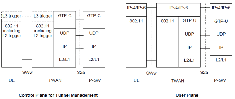
Figure 16.1.4-1: Protocols for control and user planes of GTP-based S2a for Transparent Single-Connection mode
(⇒ copy of original 3GPP image)
(⇒ copy of original 3GPP image)
Legend:
802.11:
This refers to Layer 1 and Layer 2 defined by IEEE Std 802.11-2012 [64]. Layer 2 of 802.11 is used as L2 attach and detach triggers. L2 attach trigger is mandatory with IPv6 and IPv4v6 PDN Types, and optional for IPv4 PDN Type.
L3 trigger:
This refers to DHCPv4 which can be used as optional L3 attach trigger with IPv4 PDN Type.
GTP-C:
The GPRS Tunnelling Protocol control plane consists of signalling messages between the Trusted WLAN Access Gateway and the PDN-GW over the S2a interface. It is defined in TS 29.274.
GTP-U:
The GPRS Tunnelling Protocol user plane tunnels user data between the Trusted WLAN Access Gateway and the PDN-GW over the S2a interface. It is defined in TS 29.281.
UDP:
This is the transport layer protocol onto which both GTP-C and GTP-U are layered.
IPv4/IPv6:
This refers to network layer protocols. On the TWAN this includes termination of the UE-TWAN link-local protocols (e.g. IPv6 Neighbor Discovery, ARP) and forwarding of user plane IP packets between the UE-TWAN point-to-point link and the relevant S2a tunnel.

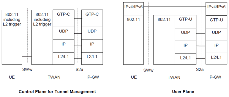
Figure 16.1.4-2: Protocols for control and user planes of GTP-based S2a for Single-Connection mode
(⇒ copy of original 3GPP image)
(⇒ copy of original 3GPP image)
Legend:
802.11:
This refers to Layer 1 and Layer 2 defined by IEEE Std 802.11-2012 [64]. Layer 2 of 802.11 is used as L2 attach and detach triggers.
GTP-C:
The GPRS Tunnelling Protocol control plane consists of signalling messages between the Trusted WLAN Access Gateway and the PDN-GW over the S2a interface. It is defined in TS 29.274.
GTP-U:
The GPRS Tunnelling Protocol user plane tunnels user data between the Trusted WLAN Access Gateway and the PDN-GW over the S2a interface. It is defined in TS 29.281.
UDP:
This is the transport layer protocol onto which both GTP-C and GTP-U are layered.
IPv4/IPv6:
This refers to network layer protocols.

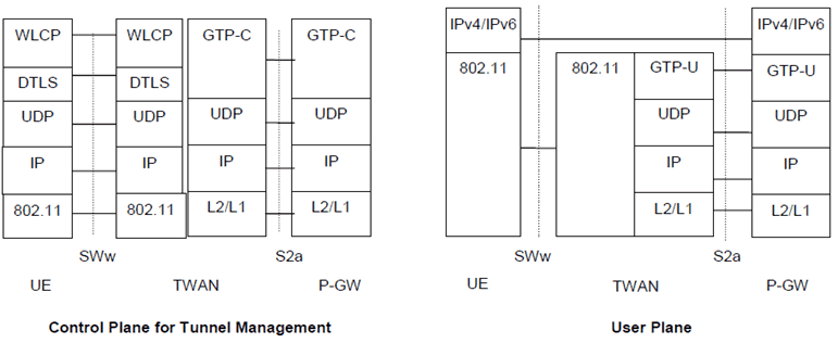
Figure 16.1.4-3: Protocols for control and user planes for GTP-based S2a for Multi-Connection mode
(⇒ copy of original 3GPP image)
(⇒ copy of original 3GPP image)
Legend:
802.11:
This refers to Layer 1 and Layer 2 defined by IEEE Std 802.11-2012 [64]. The TWAG MAC address is used as a multiplexing identifier between multiple PDN connections which belong to the same UE.
WLCP:
WLAN Control Protocol (WLCP) is used to establish and release PDN connections. The functionality of WLCP is defined in 16.1.4A.3.1.
GTP-C:
The GPRS Tunnelling Protocol control plane consists of signalling messages between the Trusted WLAN Access Gateway and the PDN-GW over the S2a interface. It is defined in TS 29.274.
GTP-U:
The GPRS Tunnelling Protocol user plane tunnels user data between the Trusted WLAN Access Gateway and the PDN-GW over the S2a interface. It is defined in TS 29.281.
DTLS:
Datagram Transport Layer Security (DTLS) is used to protect WLCP signalling as described in TS 33.402.
UDP:
This is the transport layer protocol onto which both GTP-C and GTP-U are layered.
IPv4/IPv6:
This refers to network layer protocols.
When PMIP based S2a is used with Trusted WLAN, the PMIPv6 protocol stacks described in clause 6.1.1 apply.
16.1.4A Control Plane |R12| p. 255
16.1.4A.1 Negotiation of connection mode p. 255
The negotiation of the connection mode (Single-Connection mode, Multi-Connection mode or Transparent Single-Connection mode) takes place during the EAP-AKA' access authentication.
- The network indicates the supported connection modes (Transparent Single-Connection mode, Single-Connection mode, Multi-Connection mode or any combination of them).
- The UE then requests either Single-Connection mode or Multi-Connection mode. If none of these modes is supported by both UE and network, Transparent Single-Connection mode is used if supported by the network. In case the UE requests Single-Connection mode, it includes also a request for either EPC-routed traffic or NSWO. In case the UE requests Single-Connection mode and EPC-routed traffic, the UE may further indicate e.g. handover, APN and PDN type.
- If both the UE and the network support Multi-Connection mode, the UE requests multi connection mode.
- The network provides an appropriate result code to the UE, depending on if the request is granted or rejected.
16.1.4A.2 EAP-AKA' extensions p. 256
EAP-AKA ' authentication signaling RFC 5448 is extended in order to negotiate the connection mode: Single-Connection mode, Multi-Connection mode or Transparent Single-Connection mode, and to carry additional information needed for single connection mode.
EAP-AKA' authentication signaling is extended in order to exchange the following parameters:
-
In the UE to network direction:
- The requested connection mode (Single-Connection mode or Multiple-Connection mode);
- If the UE requests an emergency attach, an indication that the UE requests an emergency attach;
-
In case Single-Connection mode is requested;
- The requested connectivity (NSWO or PDN connection), and
- In case the requested connectivity is a PDN connection: the PDN type (IPv4, IPv6, or IPv4v6), an optional hand-over indicator, optionally the requested APN (mandatory if the handover indication is provided), optionally a Protocol Configuration Options (PCO)
-
In the network to UE direction:
- The supported network connection modes (Transparent Single-Connection mode and/or Single Connection mode and/or Multi Connection mode);
- An indication on whether the network supports emergency services;
-
In case Single-Connection mode is requested:
- Whether the requested connectivity (NSWO or a PDN connection) has been granted;
- For PDN connection: the Selected APN, the selected PDN type (IPv4, IPv6, or IPv4v6), and optionally Protocol Configuration Options (PCO), Session Management back-off timer.
-
In case Multi-Connection mode was requested:
- Whether NSWO is allowed or not.
- The TWAG IP address(es) of the control plane to be used for WLCP.
16.1.4A.3 PDN connection management Control plane p. 256
16.1.4A.3.1 WLAN Control Protocol (WLCP) p. 256
WLCP is a control protocol between UE and TWAG. It applies to the support of Multi-Connection mode and enables management of PDN connectivity over a Trusted WLAN Access Network.
WLCP provides session management functionality required for:
- Establishment of PDN connections;
- Establishment of multiple bearers per PDN connection;
- Handover (from a 3GPP access) of PDN connections;
- Request the release of a PDN connection by the UE or notify the UE of the release of a PDN connection;
-
IP address assignment (i.e. delivery of the IPv4 address through WLCP);
The following PDN parameters are used:
- APN, PDN/PDP type, UE IP address/prefix, Protocol Configuration Options (PCO), Request type (initial request, handover) and optionally a Session Management back-off timer;
- The TWAG MAC address associated to the PDN connection or to the bearer.
- For emergency services, an indication that the UE has requested a PDN connection for emergency services.
- Traffic Filter Templates (TFTs) and Bearer QoS information;
- via IPv6 with link local addressing scope;
- via IPv4.
16.1.4B User plane |R12| p. 257
16.1.4B.1 User plane for PDN connection p. 257
There is a one-to-one mapping between the PDN connection or WLCP bearer, if applicable, and the S2a tunnel, and there is a one-to-one mapping between the PDN connection or S2a bearer, if applicable, and the point-to-point link between UE and TWAG. When the PDN connection is established during the UE initiated WLCP procedure, the TWAG sends a MAC address, which is specific for the PDN connection, to UE to be used by the UE as the MAC address of the TWAG for user plane packets on the default bearer. When additional S2a bearers are created for a PDN connection, the TWAG sends, when applicable, a MAC address, which is specific for the S2a bearer. The TWAG maintains the mapping between the MAC address and the S2a bearer.
The UE also maintains the mapping between the PDN connection or WLCP bearer, if applicable, and the TWAG MAC address corresponding to the PDN connection or WLCP bearer, if applicable, received during the WLCP procedure.
16.1.5 IP address allocation p. 258
16.1.5.1 General |R12| p. 258
In this Release of the specification, deferred IPv4 address allocation is not supported.
When using Single-connection mode and Multi-connection mode, the UE sees the PDN Connection as a point-to-point link similar to how it is in 3GPP access. Shared link parameters such as netmask and default router IP address are not used.
In Transparent Single-connection Mode, TWAG shall act as DHCPv4/v6 server for the UE.
In Single-connection mode and Multi-connection mode, the link model is described below:
- To support IPv4 connectivity, the IPv4 address shall be allocated and sent to the UE during PDN connection establishment.
- To support IPv6 connectivity, the PGW handles the RS/RA messages in GTP-based S2a scenario, while the TWAG handles the RS/RA messages in PMIP-based S2a scenario.
- To support IPv6 parameter configuration UE may use stateless DHCPv6. The PGW acts as DHCPv6 server. With PMIP-based S2a the TWAG may act as DHCPv6 relay.
16.1.5.2 IP address allocation in Transparent Single-Connection Mode |R12| p. 258
In order to enable IPv4 connectivity the TWAN shall support DHCPv4 server functionality for IPv4 parameter configuration and IP address allocation as specified in RFC 2131 and RFC 4039. For this case the following applies:
- If the PDN type in the user subscribtion data is IPv4 or IPv4v6, the TWAN requests IPv4 address in the Proxy Binding Update or GTP Create Session Request from the PDN-GW. The IPv4 address is delivered to the TWAN during the PMIPv6 or GTP tunnel establishement. When the UE requests the IPv4 address via DHCPv4, the TWAN delivers the received IPv4 address to the UE within DHCPv4 signalling after the PMIPv6 or GTP tunnel is established between the TWAN and the PDN-GW.
16.1.5.3 IP address allocation in Single-Connection Mode |R12| p. 259
Similar mechanism as described in clause 5.3.1.1 of TS 23.401 is used to decide the PDN type, with the following exceptions:
- The UE indicates the requested PDN type during EAP authentication procedure.
- The TWAG selects the PDN type according to the subscription data in the same way as the MME selects it when 3GPP access is used, as described in TS 23.401.
- If the requested PDN type is IPv4v6, and both IPv4 and IPv6 PDN types are allowed by subscription but not IPv4v6, the TWAG shall set the PDN type to IPv4 or IPv6 where the selection between IPv4 and IPv6 is implementation specific. Then the UE shall not initiate the UE requested PDN connectivity procedure to this APN in order to activate a second PDN connection with the other single address PDN type.
- The PDN-GW shall allocate and send the IPv4 address to the TWAG in the Create Session Response or Proxy Binding Acknowledgement message. The IPv4 address received from the PDN-GW is provided to the UE during the EAP authentication procedure. The PDN-GW also sends IPv4 configuration parameters to the UE via PCO.
- With GTP-based S2a, the PDN-GW shall allocate and send the IPv6 network prefix to the UE in RA message. Because any prefix that the PDN-GW will advertise to the UE is unique, there is no need for the UE to perform Duplicate Address Detection for global uniqueness for any IPv6 address configured from the allocated IPv6 network prefix. However, the PDN-GW shall respond with Neighbor Advertisement upon receiving Neighbor Solicitation messages from a given UE. For example, the UE may perform Neighbor Unreachability Detection towards the PGW, the PGW supports the DAD related functionality as described in TS 23.401. Moreover, to ensure that link-local address generated by the UE does not collide with the link-local address of the PGW, the PDN-GW shall provide an interface identifier to the UE and the UE shall use this interface identifier to configure its link-local address.
- With PMIP-based S2a, the PDN-GW shall allocate and send the IPv6 network prefix to the TWAG in the Proxy Binding Acknowledgement. The TWAG sends it to the UE in RA message. Because any prefix that the TWAG will advertise to the UE is unique, there is no need for the UE to perform Duplicate Address Detection for global uniqueness for any IPv6 address configured from the allocated IPv6 network prefix. However, TWAG shall respond with Neighbor Advertisement upon receiving Neighbor Solicitation messages from a given UE, similar to that supported by PGW in the case of GTP based S5/S8 described in clause 5.3.1.2.2 of TS 23.401. Otherwise the PGW has the same functions as it is defined in clause 5.3.1.2.2 of TS 23.401. Moreover, to ensure that link-local address generated by the UE does not collide with the link-local address of the TWAG, the PDN-GW shall provide an interface identifier to the UE and the UE shall use this interface identifier to configure its link-local address. The PDN-GW shall also provide a link-local address to the TWAG and the TWAG shall use the link-local address on the access link shared with the UE.
- The PGW may support DHCPv6 server functionality for IPv6 parameter configuration as specified in RFC 3736. When the UE requests IPv6 parameter configuration via DHCPv6 procedure, the TWAG delivers DHCPv6 signallings between the UE and the PGW as a DHCPv6 relay in PMIP-based S2a scenario.
- The TWAG shall request both IPv6 network prefix and IPv4 address in the Create Session Request or Proxy Binding Update message.
- The IPv4 address allocation and IPv4 parameter configuration are the same as for PDN type IPv4 defined in previous bullets.
- The IPv6 network prefix allocation via IPv6 Stateless Address auto-configuration procedure and IPv6 parameter configuration via Stateless DHCPv6 procedure are the same as for PDN type IPv6 defined in previous bullets.
16.1.5.4 IP address allocation in Multi-Connection Mode |R12| p. 260
Similar mechanism as described in clause 5.3.1.1 of TS 23.401 is used to decide the PDN type, with the following exceptions:
- The UE indicates the request PDN type in WLCP signalling.
- The TWAG selects the the PDN type according to the subscription data received from the HSS/AAA in the same way as the MME selects it when 3GPP access is used, as described in TS 23.401.
- The PDN-GW shall allocate and send the IPv4 address to the TWAG in the Create Session Response or Proxy Binding Acknowledgement message. The TWAG shall send the IPv4 address received from the PDN-GW to the UE in WLCP message. The PDN-GW also sends IPv4 configuration parameters to the UE via PCO.
- The same considerations as above for PDN type IPv6 in single connection mode apply.
- The TWAG shall request both IPv6 network prefix and IPv4 address in the Create Session Request or Proxy Binding Update message.
- The IPv4 address allocation and IPv4 parameter configuration are the same as for PDN type IPv4 defined in previous bullets.
- The IPv6 network prefix allocation via IPv6 Stateless Address auto-configuration procedure and IPv6 parameter configuration via Stateless DHCPv6 procedure are the same as for PDN type IPv6 defined in previous bullets.