Content for TS 23.402 Word version: 18.3.0
0…
4…
4.2…
4.2.2
4.2.3
4.3…
4.4…
4.5…
4.5.7…
4.6…
4.7…
4.7.2…
4.8…
4.8.2a…
4.9…
5…
5.2…
5.4…
5.5
5.6…
5.7…
5.8…
6…
6.2…
6.3
6.4…
6.4.3…
6.5…
6.6…
6.7…
6.8…
6.10…
6.13…
6.15…
7…
7.2…
7.3
7.4…
7.5…
7.6…
7.8…
7.10…
8…
8.2.1.2
8.2.1.3…
8.2.2
8.2.3…
8.2.6…
8.3…
8.4…
8.5…
9…
9.3…
9.4…
10…
13…
16…
16.1.2…
16.1.6…
16.2…
16.2.1a…
16.3…
16.4…
16.7…
16.8…
16.10…
17…
A…
C…
E…
5.2 Initial E-UTRAN Attach with PMIP-based S5 or S8 p. 88
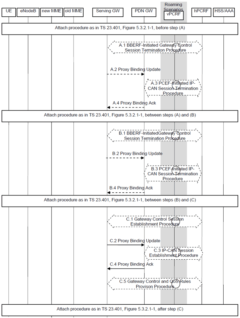
This clause is related to the case when the UE powers-on in the LTE network with PMIP-based S5 or S8 interface and includes the case of roamers from a GTP network into a PMIPv6 network when PMIP-based S5 is used to connect the Serving-GW and the PDN-GW of the visited PLMN. Proxy Mobile IP version 6 is used on S5 or S8 interface. It is assumed that the MAG is collocated with the Serving-GW for the PMIPv6 procedure between the Serving-GW and the PDN-GW.
When only GTP-based S5 or S8 connections are established for roamers from a GTP network into a PMIPv6 network the procedure as described in TS 23.401 applies.

This procedure applies to the Non-Roaming (Figure 4.2.1-1), Roaming (Figure 4.2.1-2) and Local Breakout (Figure 4.2.3-4) cases. For the Roaming and Local Breakout cases, the vPCRF forwards messages between the Serving-GW and the hPCRF. In the Local Breakout case, the vPCRF forwards messages between the PDN-GW and the hPCRF.
This procedure is also used to establish the first PDN connection over E-UTRAN with PMIP based S5 or S8 when the UE already has active PDN connections only over a non-3GPP access network and wishes to establish simultaneous PDN connections to different APNs over multiple accesses.
The optional interaction steps between the gateways and the PCRF in the procedures in Figure 5.2-1 only occur if dynamic policy provisioning is deployed. Otherwise policy may be statically configured with the gateway.
A.1)
Steps between A.4 and B.1 and steps between B.4 and C.1 are described in clause 5.3.2.1 of TS 23.401.
Steps B.1 to B.4 are the same as Steps A.1 through A.4.
The Serving-GW initiates the Gateway Control Session Termination Procedure with the PCRF, as specified in TS 23.203. The S-GW provides information to enable the PCRF to uniquely identify the IP-CAN session. This results in the removal of the Gateway Control session in S-GW.
A.2)
The Serving-GW sends a Proxy Binding Update (MN NAI, lifetime=0) message to the PDN-GW. The MN NAI identifies the UE. The lifetime field indicates that the message is used to de-register the UE at the PDN-GW.
A.3)
The PDN-GW initiates the IP-CAN session Termination Procedure with the PDN-GW as specified in TS 23.203. The PDN-GW provides information to enable the PCRF to uniquely identify the IP-CAN session. This results in the removal of IP-CAN session related information in the PCRF and in the PDN-GW.
A.4)
The PDN-GW responds to the Serving-GW with the result of the deregistration with Proxy Binding Update Acknowledgement message.
C.1)
After steps C.1-C.5 the procedure continues as it is defined in clause 5.3.2 of TS 23.401 with the exception that the steps in block D are not performed.
The Serving-GW initiates the Gateway Control Session Establishment Procedure with the PCRF, as specified in TS 23.203. The S-GW provides the information to the PCRF to correctly associate it with the IP-CAN session to be established in step C.3 and also to convey subscription related parameters to the PCRF that have been received between steps (B) and (C) from the MME, including the APN-AMBR and Default Bearer QoS. The Serving-GW provides in addition the UE Location Information IE and user CSG information, if available. The Serving-GW also indicates its support for the extended TFT filter format.
In the case of Emergency Attach, if the IMSI provided by the MME to the S-GW in step before C.1 is marked as unauthenticated, the SGW provides this IMSI marked as unauthenticated to the PCRF in the GW Control Session Establishment. This IMSI marked as unauthenticated is provided by the PCRF to the PDN-GW in step C.3. In this case, the IMEI is used as the UE Identity in the message to the PCRF.
C.2)
The Serving-GW sends a Proxy Binding Update (MN NAI, Lifetime, Access Technology Type, Handover Indicator, APN, GRE key for downlink traffic, UE Address Info Additional Parameters, Charging Characteristics) to the PDN-GW in order to establish the new registration. The MN NAI identifies the UE for whom the message is being sent. The Lifetime field must be set to a nonzero value in the case of a registration. Access Technology Type is set to indicate 3GPP access to EPS. Handover Indication option is set to indicate attachment over a new interface as no Handover indication is received from the MME. The APN may be necessary to differentiate the intended PDN from the other PDNs supported by the same PDN-GW. The Serving-GW includes the EPS bearer identity of the default bearer received from the MME if multiple PDN connections to the same APN are supported. The optional Additional Parameters may contain information, for example, protocol configuration options. The UE Address Info IE is used to request an IPv6 prefix, IPv4 address, or both IPv4 address and IPv6 prefix. Based on PDN Type parameter received in the Create Session Request, Serving-GW includes request for IPv4 Home Address (PDN Type set to IPv4), or IPv6 Home Network Prefix (PDN type set to IPv6) or both IPv4 home address and IPv6 HNP (PDN type set to IPv4v6) in the PBU as specified in PMIPv6 specification, RFC 5213). In the case of a subscribed IPv4 address and/or IPv6 prefix provided by the MME in the PDN Address Allocation IE, the UE Address Info IE is set to the subscribed IPv4 address and/or IPv6 prefix.
In case of Emergency Attach, if IMSI is not provided by MME to SGW or the IMSI provided is marked as unauthenticated, the S-GW creates MN NAI based on IMEI as specified in TS 23.003.
C.3)
The PDN-GW initiates the IP-CAN Session Establishment Procedure with the PCRF, as specified in TS 23.203. The PDN-GW provides information to the PCRF used to identify the session and associate Gateway Control Sessions established in step C.1 correctly. The PDN-GW also provide the PCRF with the UE IPv4 address and/or IPv6 prefix newly assigned as a result of step C.2, which might lead the PCRF to update the QoS rules to include this IPv4 address and/or IPv6 prefix. The PCRF creates IP-CAN session related information and responds to the PDN-GW with PCC rules UE Location Information IE, user CSG information, if received from the Serving-GW, and event triggers.
In case of Emergency Attach, if MN NAI based on IMEI is received in the PBU message in step C.2, the PDN-GW uses the IMEI as a UE Identity in the message to the PCRF.
C.4)
The PDN-GW responds with a PMIPv6 Binding Acknowledgement (MN NAI, Lifetime, UE Address Info, GRE key for uplink traffic, Charging ID, Additional Parameters) message to the Serving-GW. The MN NAI is identical to the MN NAI sent in the Proxy Binding Update. The Lifetime indicates the duration the binding will remain valid. The PDN-GW takes into account the request from Serving-GW and the policies of operator when the PDN-GW allocates the UE Address Info. The UE address info returns the newly assigned IPv4 address and/or IPv6 prefix assigned to the UE, if one was requested in the PMIPv6 Proxy Binding Update message. IP address allocation by the PDN-GW is as stated in clause 4.7.1. "IP Address Allocation with PMIP-based S5/S8". If the PDN-GW sends the DHCPv4 Address Allocation Procedure Indication in the Proxy Binding Acknowledgement message, the UE IPv4 address assigned by the PDN-GW is not provided as part of the default bearer activation procedures to the UE. In this case, the Serving-GW does not forward the IPv4 address assigned by the PDN-GW to the MME, but sets the PDN Address to 0.0.0.0 in the message to the MME. If a valid IPv4 address and/or IPv6 prefix received in the Proxy Binding Update message, the PDN-GW validates the addresses and returns it the UE Address Info IE of the Proxy Binding Acknowledge message. If the corresponding Proxy Binding Update contains the EPS bearer identity, the PDN-GW shall acknowledge if multiple PDN connections to the given APN are supported. The Charging ID is assigned for the PDN connection for charging correlation purposes. The optional Additional Parameter information element may contain other information, including for example Protocol Configuration Options.
C.5)
The PCRF initiates the Gateway Control and QoS Rules Provision Procedure specified in TS 23.203 by sending a message with the QoS rules and Event Trigger information to the S-GW. The PCRF also indicates whether the extended TFT filter format is to be supported for the PDN connection.
5.3 Detach for PMIP-based S5/S8 p. 91
The procedure in this clause provides the PMIPv6-based S5/S8 variants to all E-UTRAN Detach Procedures, including UE, MME or HSS initiated detach procedure (clause 5.3.8 of TS 23.401).
In case of detach, all the bearers at the Serving-GW are terminated. Further, the IP-CAN session for the UE in the PDN-GW is also terminated.
If the UE is connected to both E-UTRAN and a non-3GPP access before the UE triggers detach on E-UTRAN, and the UE wants to preserve all or a subset of the active PDN connections routed over E-UTRAN system, a UE initiated PDN disconnection procedure shall be performed for each of the PDN connections that are not required to be preserved. The UE then shall initiate the applicable handover procedure to transfer to the access system through which the UE remains attached to the Evolved Packet Core each of the PDN connections to be preserved.

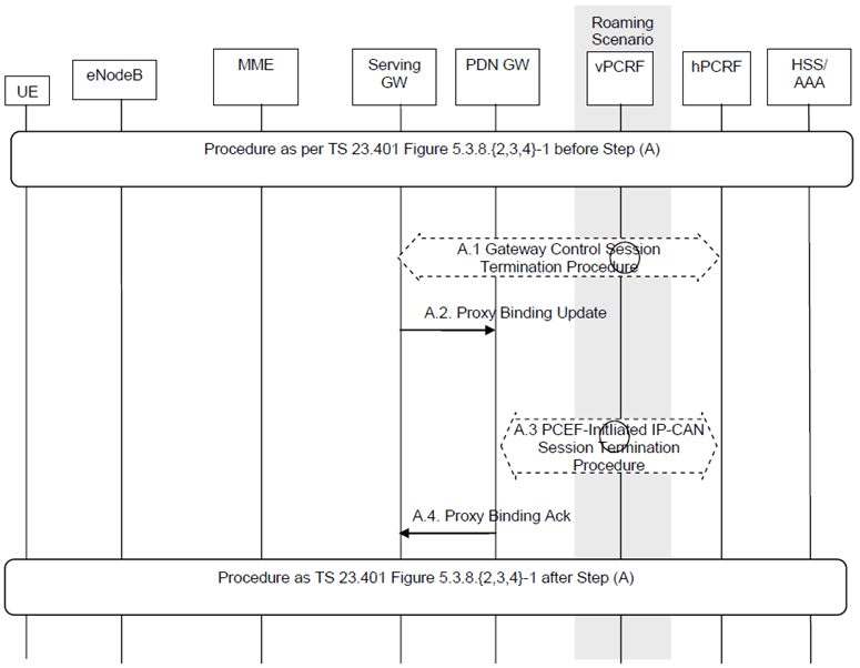
The optional interaction steps between the gateways and the PCRF in Figure 5.3-1 only occur if dynamic policy provisioning is deployed. Otherwise policy may be statically configured with the gateway.
This procedure applies to the Non-Roaming (Figure 4.2.1-1), Roaming (Figure 4.2.1-2) and Local Breakout (Figure 4.2.3-4) cases. For the Roaming and Local Breakout cases, the vPCRF forwards messages between the Serving-GW and the hPCRF. In the Local Breakout case, the vPCRF forwards messages between the PDN-GW and the hPCRF.
In the non-roaming case, the vPCRF is not involved at all.
A.1)
The Serving-GW initiates the Gateway Control Session Termination Procedure with the PCRF as specified in TS 23.203. The S-GW provides information to enable the PCRF to unambiguously identify the IP-CAN session corresponding to the Gateway Control Session and indicates User Location Information and/or UE Time Zone Information to the PCRF as an Event Report if the corresponding event trigger is set. This results in the removal of the Gateway Control session in S-GW.
A.2)
The Serving-GW sends a Proxy Binding Update (MN NAI, APN, lifetime=0) message to the PDN-GW to release the PDN connection of the UE at the PDN-GW. If only one PDN connection per APN is supported then the MN NAI and the APN identify the PDN connection of the UE. If multiple PDN connections per APN are supported then the MN NAI, the APN and the EPS bearer identity of the default bearer identify the PDN connection of the UE. The lifetime field indicates that the message is used to release the PDN connection of the UE at the PDN-GW.
A.3)
The PDN-GW initiates the PCEF-Initiated IP-CAN Session Termination Procedure with the PCRF as specified in TS 23.203. The PDN-GW provides information to enable the PCRF to uniquely identify the IP-CAN session. This results in the removal of IP-CAN session related information in the PCRF and in the PDN-GW.
A.4)
The PDN-GW responds to the Serving-GW with the result of the PDN connection release with Proxy Binding Update Acknowledgement