Content for TS 23.402 Word version: 18.3.0
0…
4…
4.2…
4.2.2
4.2.3
4.3…
4.4…
4.5…
4.5.7…
4.6…
4.7…
4.7.2…
4.8…
4.8.2a…
4.9…
5…
5.2…
5.4…
5.5
5.6…
5.7…
5.8…
6…
6.2…
6.3
6.4…
6.4.3…
6.5…
6.6…
6.7…
6.8…
6.10…
6.13…
6.15…
7…
7.2…
7.3
7.4…
7.5…
7.6…
7.8…
7.10…
8…
8.2.1.2
8.2.1.3…
8.2.2
8.2.3…
8.2.6…
8.3…
8.4…
8.5…
9…
9.3…
9.4…
10…
13…
16…
16.1.2…
16.1.6…
16.2…
16.2.1a…
16.3…
16.4…
16.7…
16.8…
16.10…
17…
A…
C…
E…
8.2.6 Non-3GPP IP Access to 3GPP Access Handover with PMIPv6 on S2a/b for Chained PMIP-based S8
8.2.7 3GPP Access to Non-3GPP IP Access Handover with PMIPv6 on S2a/b for Chained PMIP-based S8
...
...
8.2.6 Non-3GPP IP Access to 3GPP Access Handover with PMIPv6 on S2a/b for Chained PMIP-based S8 p. 203
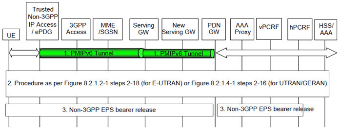
The steps involved in the handover from a trusted or non-trusted non-3GPP IP access to a 3GPP access connected to EPC are depicted below for roaming cases with chained S2a/b and PMIP-based S8. It is assumed that while the UE is served by the non-3GPP IP access, a PMIPv6 tunnel is established between the non-3GPP access network and the Serving-GW and another one between the Serving-GW and the PDN-GW.

Figure 8.2.6-1: Handover from Trusted or Untrusted Non-3GPP IP Access to 3GPP Access with chained S2a/b and PMIP-based S8
(⇒ copy of original 3GPP image)
(⇒ copy of original 3GPP image)
In case of handover to E-UTRAN, the following applies for connectivity to multiple PDNs:
- If the UE is connected to both 3GPP access and non-3GPP access before the handover of PDN connections to 3GPP access is triggered, the procedure as per Figure 8.2.1.2-1 before step 18 shall be skipped and the UE shall only perform step 18 of Figure 8.2.1.2-1 for each PDN connection that is being transferred from non-3GPP access.
- If the UE is connected only to non-3GPP access before the handover of PDN connections to 3GPP access is triggered, the procedure as per Figure 8.2.1.2-1 before step 18 shall be performed. In step 3 of Figure 8.2.1.2-1 the UE shall provide an APN corresponding to one of the PDN connections that are being transferred from non-3GPP access. The UE shall then repeat step 18 of Figure 8.2.1.2-1 for each of the remaining PDN connections that are being transferred from 3GPP access.
- If the UE is connected to both 3GPP access and non-3GPP access before the handover of PDN connections to 3GPP access is triggered, steps 2 to 6 of Figure 8.2.1.4-1 shall be skipped.
- If the UE is connected only to non-3GPP access before the handover of PDN connections to 3GPP access is triggered, steps 2 to 6 of Figure 8.2.1.4-1 shall be performed.
- The UE shall repeat steps 7 to 16 of Figure 8.2.1.4-1 for each PDN connection that is being transferred from non-3GPP access.
- The UE uses a trusted or untrusted non-3GPP access system. PDN connectivity is achieved through concatenated PMIPv6 tunnels between the trusted non-3GPP access or ePDG and the Serving-GW, and between the Serving-GW and the PDN-GW.
- The handover procedure from trusted or untrusted non-3GPP IP access with PMIPv6 on S2a/S2b to 3GPP access with PMIP-based S5/S8 is performed as described in steps 2-18 of clause 8.2.1.2 (for E-UTRAN) and steps 2-16 of clause 8.2.1.4 (for UTRAN/GERAN).
- In case a new Serving-GW has been selected during the attach on 3GPP access, the PDN-GW triggers the bearer release in the non-3GPP access as defined in clause 6.12.3. Otherwise, the Serving-GW triggers resource release in the non-3GPP access as defined in steps 2-5 of clause 6.12.3.
8.2.7 3GPP Access to Non-3GPP IP Access Handover with PMIPv6 on S2a/b for Chained PMIP-based S8 p. 204
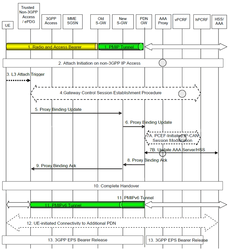
The steps involved in the handover from a 3GPP access to a trusted or non-trusted non-3GPP IP access connected to EPC are depicted below for roaming cases with chained S2a/b and PMIP-based S8.

Figure 8.2.7-1: Handover from 3GPP IP Access to Trusted or Untrusted Non-3GPP Access with chained S2a/b and PMIP-based S8
(⇒ copy of original 3GPP image)
(⇒ copy of original 3GPP image)
For connectivity to multiple PDNs the following applies:
- If the UE is connected to both 3GPP access and non-3GPP access before the handover of PDN connections to non-3GPP access is triggered, steps 2 to 11 shall be skipped and the UE shall only perform step 12 for each PDN connection that is being transferred from 3GPP access.
- If the UE is connected only to 3GPP access before the handover of PDN connections to non-3GPP access is triggered, steps 2 to 11 shall be performed. In step 3 the UE shall provide an APN corresponding to one of the PDN connections that are being transferred from 3GPP access. The UE shall then repeat step 12 for each of the remaining PDN connections that are being transferred from 3GPP access.
- Step 13 shall be repeated for each PDN connection that is being transferred from 3GPP access.
Step 1.
The UE is connected to the PDN via a 3GPP Access and has a PMIPv6 tunnel on the S8 interface.
Step 2.
The attach initiation on the trusted or untrusted non-3GPP access is performed as described in steps 2-3 of clause 8.2.2 (for trusted non-3GPP access) and steps 2-3 of clause 8.2.3 (for untrusted non-3GPP access). As part of the authentication procedure, the 3GPP AAA proxy obtains the PDN-GW identity from the HSS/AAA as described in clause 4.5.1, and performs Serving-GW selection as described in clause 4.5.3. Both PDN-GW identity and Serving-GW information is provided to the MAG function of the trusted non-3GPP access or ePDG. If PCC is deployed, the MAG function of the Trusted Non-3GPP IP access is notified to interact with the PCRF when it is the PMIP-based chained case.
Step 3.
After successful authentication and authorization, the L3 attach procedure in the trusted non-3GPP access is triggered as described in step 4 of clause 8.2.2.
Step 4.
The trusted non-3GPP access initiates a Gateway Control Session Establishment Procedure with the PCRF as described in step 5 of clause 8.2.2.
Step 5.
The MAG function of Trusted Non-3GPP IP Access or ePDG sends a Proxy Binding Update (MN-NAI, Lifetime, Access Technology Type, Handover Indicator, APN, GRE key for downlink traffic, PDN-GW address, Additional Parameters) message to the Serving-GW in the VPLMN. The MN NAI identifies the UE. The Lifetime field must be set to a nonzero value, indicating registration. Access Technology Type is set to a value matching the characteristics of the non-3GPP access. Handover Indicator is set to indicate handoff between two different interfaces of the UE. The MAG creates and includes a PDN connection identity if the MAG supports multiple PDN connections to a single APN. The Additional Parameters may include Protocol Configuration Options and other information.
Step 6.
The Serving-GW sends a corresponding Proxy Binding Update (MN-NAI, Lifetime, Access Technology Type, Handover Indicator, APN, GRE key for downlink traffic, Additional Parameters) message (as in step 3) to the PDN-GW. If the MAG included the PDN connection identity in the Proxy Binding Update of the previous step and the Serving-GW supports multiple PDN connections to a single APN then the Serving-GW forwards the PDN connection identity to the PDN-GW.
Step 7A.
The PDN-GW initiates the PCEF-Initiated IP-CAN Session Modification Procedure with the hPCRF to update the rules in the PDN-GW, as specified in TS 23.203.
Step 7B.
The PDN-GW informs the 3GPP AAA Server of its PDN-GW identity and the APN corresponding to the UE's PDN Connection and obtains authorization information from the 3GPP AAA Server. The message includes information that identifies the PLMN in which the PDN-GW is located. The 3GPP AAA Server may update the information registered in the HSS as described in clause 12.
Step 8.
The PDN-GW processes the proxy binding update and creates a binding cache entry for the PMIPv6 tunnel towards the Serving-GW. The PDN-GW responds with a Proxy Binding Acknowledgement (MN-NAI, Lifetime, UE Address Info, GRE key for uplink traffic, Additional Parameters) message to the Serving-GW. The MN-NAI is identical to the MN-NAI sent in the Proxy Binding Update. The Lifetime indicates the duration the binding will remain valid. The UE Address Info includes one or more IP addresses. If the corresponding Proxy Binding Update contains a PDN connection identity, the PDN-GW shall acknowledge if the PDN-GW supports multiple PDN connections to a single APN. The Additional Parameters may include Protocol Configuration Options and other information. The Additional Parameters may include Protocol Configuration Options and other information.
Step 9.
The Serving-GW processes the proxy binding acknowledgement and creates a binding cache entry for the PMIPv6 tunnel towards the MAG function in the trusted non-3GPP access or ePDG. At this point, the Serving-GW also establishes the internal forwarding state for the concatenation of the PMIPv6 tunnels. The Serving-GW then sends a corresponding Proxy Binding Acknowledgement (MN-NAI, Lifetime, UE Address Info, GRE key for uplink traffic, Charging ID, Additional Parameters) message (as in step 8) to the MAG function of Trusted Non-3GPP IP Access or ePDG.
Step 10.
The handover attach procedure is completed as described in step 9 of clause 8.2.2 (for trusted non-3GPP access) and steps 7-8 of clause 8.2.3 (for untrusted non-3GPP access).
Step 11.
The UE is connected to the PDN via the non-3GPP access system. PDN connectivity is achieved through concatenated PMIPv6 tunnels between the trusted non-3GPP access or ePDG and the Serving-GW, and between the Serving-GW and the PDN-GW.
Step 12.
For connectivity to multiple PDNs, the UE establishes connectivity to each PDN that is being transferred from 3GPP access, besides the PDN connection established in steps 2-11, by executing the UE-initiated Connectivity to Additional PDN procedure specified in clause 6.8.1.2, that applies to both trusted and untrusted non-3GPP accesses.
Step 13.
In case a new Serving-GW has been selected during the attach on the non-3GPP access, the PDN-GW triggers the bearer release in the 3GPP access using the PDN-GW initiated Bearer Deactivation procedure. Otherwise, the Serving-GW triggers the bearer release in the 3GPP Access using the Serving-GW initiated Bearer Deactivation procedure. The 3GPP access resources associated with the PDN address are released if existing.