Content for TS 23.228 Word version: 19.1.0
1…
3…
4…
4.2.4…
4.3…
4.4…
4.13…
4.16…
5…
5.2…
5.3…
5.4…
5.4.7…
5.4.8…
5.4a…
5.5…
5.5.3…
5.6…
5.6.3…
5.7…
5.7.3…
5.7.5…
5.7.8…
5.8…
5.10…
5.11…
5.11.3…
5.11.3.3
5.11.3.4
5.11.4…
5.11.5…
5.11.5.3…
5.11.6…
5.12…
5.16…
5.16.2…
5.19…
5.20…
A…
E…
E.2.2…
G…
G.5…
H
I…
J…
K…
L…
M…
M.3…
N…
P…
Q…
Q.2.5…
R…
S…
T…
U…
U.2…
V…
W…
X…
Y…
Z…
AA…
AA.3…
AB…
AC…
AC.7…
AC.7.2…
AC.7.2.2
AC.7.2.3…
AC.7.4…
AC.7.9…
AC.7.9.3…
AC.7.10…
AC.7.10.4.2…
AC.9…
AC.10…
AC.11…
AD…
AE…
AF…
AG…
AC.7.9.3 Signalling Procedure of Application Data Channel Interworking via DC AS
AC.7.9.4 Signalling Procedure of Application Data Channel Interworking via DC AS for originating MTSI UE
...
...
AC.7.9.3 Signalling Procedure of Application Data Channel Interworking via DC AS p. 394
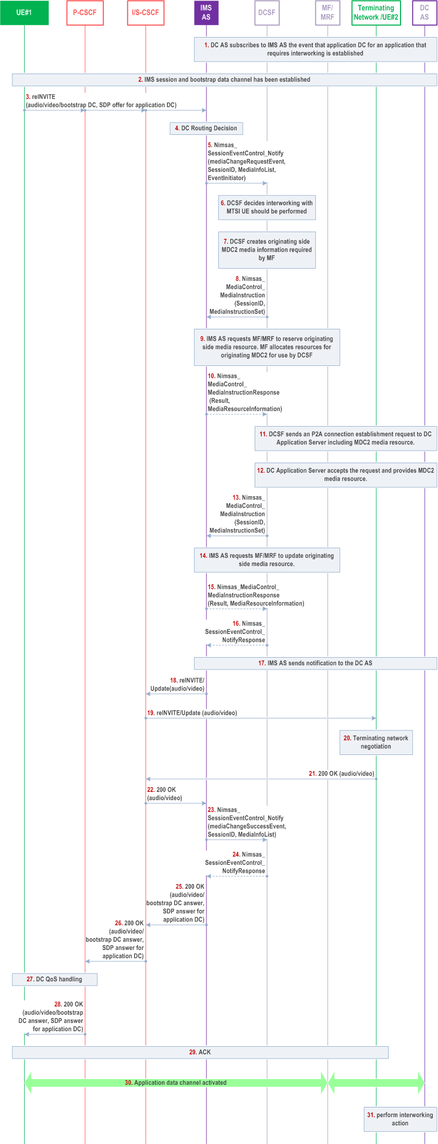
Figure AC.7.9.3-1 depicts a signalling flow diagram for establishing an application data channel from DCMTSI UE to DC application server, providing interworking of application data channel to MTSI UE via DC application server.
The originating DCMTSI UE sends the data channel application media to the DC AS, which performs the necessary interworking actions on the application media for the terminating MTSI UE.

The steps in the call flow are as follows:
Step 1.
DC AS subscribes via the NEF to be notified when any application DC for a DC application that requires interworking is established.
Step 1a.
Step 2.
The DC AS subscribes to the NEF by using Nnef_ImsEE_Subscribe Request (event ID: DC Interworking Required, DC Interworking Information). The DC Interworking Information includes the application ID(s) of the DC application which requires interworking with MTSI UE.
Step 1b.
The NEF responses to DC AS by using Nnef_ImsEE_Subscribe Response.
Step 1c.
The NEF locates the IMS AS(s) via NRF.
Step 1d.
The NEF subscribes to the IMS AS as requested by DC AS in step 1a, by using Nimsas_ImsEE_Subscribe Request.
Step 1e.
The IMS AS responses to NEF by using Nimsas_ImsEE_Subscribe Reponse.
IMS session and bootstrap data channel have been established. Selected DC application(s) have been downloaded to UE#1.
The DCSF knows the UE#2 or terminating network does not support IMS DC based on procedure in clause AC.7.9.1. Hence, the bootstrap data channel is established only between the UE#1 and the originating network.
Step 3-5.
The UE#1 initiates a P2P application DC. Steps 1-2 of clause AC.7.2.1 applies.
Step 6.
After receiving the session event notification from the IMS AS, the DCSF determines that IMS DC interworking for the requested DC application is to be performed based on the application information, i.e. application id. the remote network or UE#2 not supporting IMS DC, or not willing to use IMS DC. The DCSF changes P2P application DC to P2A application DC.
Step 6a.
Step 7.
The DCSF informs to the IMS AS that IMS DC interworking action is required for the requested DC application and the UE#2 side Information. The UE#2 side Information may include the SIP URI of the UE#2 or Called ID.
Step 6b.
The IMS AS notifies to the NEF that the DC Interworking Required event is detected with the UE#2 side Information by using Nimsas_ImsEE_Notify Request.
Step 6c.
The NEF responses to the IMS AS by using Nimsas_ImsEE_Notify Response.
Step 6d.
The NEF notifes to the DC AS that the DC Interworking Required event is detected with the UE#2 side Information by using Nnef_ImsEE_Notify Request.
Step 6e.
The DC AS responses to the NEF by using Nnef_ImsEE_Notify Response.
The DCSF instructs the MF via the IMS AS to establish the media resource of the P2A application DC and the DC connection is established between UE and the DC AS. During P2A connection establishment, the DC AS takes into account the information received in step 6d. Steps 5-14 of clause AC.7.2.2 applies.
Step 8-9.
IMS AS sends the re-INVITE to remote network side and UE#2,which does not include bootstrap data channel information and application data channel media components in the SDP.
Step 10.
Steps 17-26 of clause AC.7.2.2 applies.
Step 11.
UE#1 uses the established application data channel to provide DC application specific information e.g. sends the file (e.g. a photo) to the DC AS, which will be sent to UE#2 from DC AS.
Step 12.
DC AS performs interworking actions based on the notification received in step 6d and the data received in step 11.
AC.7.9.4 Signalling Procedure of Application Data Channel Interworking via DC AS for originating MTSI UE p. 396
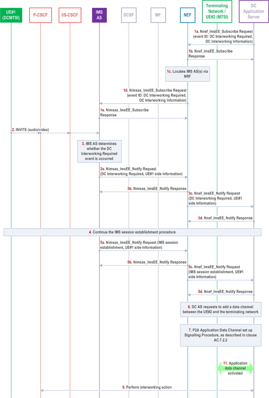
Figure AC.7.9.4-1 depicts a signalling flow diagram for establishing an application data channel from DC application server to DCMTSI UE, providing interworking of application data channel to MTSI UE via DC application server.
The DC AS initiates the procedure of application data channel setup between the serving network of the DCMTSI UE and the DCMTSI UE (terminating side), and the terminating DCMTSI UE sends the data channel application media to the DC AS. The DC AS performs the necessary interworking actions on the application media for the originating MTSI UE.

The steps in the call flow are as follows:
Step 1.
DC AS subscribes via the NEF to be notified when any application DC for a DC application that requires interworking is established.
Step 1a.
Step 2.
The DC AS subscribes to the NEF by using Nnef_ImsEE_Subscribe Request (event ID: DC Interworking Required, DC Interworking Information). The DC Interworking Information includes the UE#2 side Information which is configured as an interworking provider e.g. the service number of the customer service centre.
Step 1b.
The NEF responses to DC AS by using Nnef_ImsEE_Subscribe Response.
Step 1c.
The NEF locates the IMS AS(s) via NRF.
Step 1d.
The NEF subscribes to the IMS AS as requested by DC AS in step 1a, by using Nimsas_ImsEE_Subscribe Request.
Step 1e.
The IMS AS responses to NEF by using Nimsas_ImsEE_Subscribe Reponse.
The UE#1 initiates an IMS session with the UE#2.
Step 3.
The IMS AS determines that IMS DC interworking for the DC application served by the DC AS is to be performed based on the SDP offer received in step 2, e.g. the Called ID that matches with the service number included in the UE#2 side Information.
Step 3a.
Step 4.
The IMS AS notifies to the NEF that the DC Interworking Required event is detected with the UE#1 side Information by using Nimsas_ImsEE_Notify Request. The UE#1 side Information may include the SIP URI of the UE#1 or Calling ID.
Step 3b.
The NEF responses to the IMS AS by using Nimsas_ImsEE_Notify Response.
Step 3c.
The NEF notifies to the DC AS that the DC Interworking Required event is detected with the UE#1 side Information by using Nnef_ImsEE_Notify Request.
Step 3d.
The DC AS responses to the NEF by using Nnef_ImsEE_Notify Response.
The IMS AS sends the INVITE to remote network side and UE#2, and the IMS session establishment procedure is continued.
Step 5.
After IMS session establishment, the IMS AS notifies via the NEF that the IMS Session is established for the UEs that IMS DC interworking to be performed.
Step 5a.
Step 6.
The IMS AS notifies to the NEF that the IMS Session is established with the UE#1 side Information by using Nimsas_ImsEE_Notify Request. The notification of IMS Session establishment is implicitly subscribed in step 3b.
Step 5b.
The NEF responses to the IMS AS by using Nimsas_ImsEE_Notify Response.
Step 5c.
The NEF notifies to the DC AS that the IMS Session is established with the UE#1 side Information by using Nnef_ImsEE_Notify Request. The notification of IMS Session establishment is implicitly subscribed in step 3d.
Step 5d.
The DC AS responses to the NEF by using Nnef_ImsEE_Notify Response.
DC AS requests to the serving network of the UE#2 (terminating network) to add a local data channel for the UE#2, based on the procedure of Adding Data Channel to an Existing IMS Session as described in clause AG.2.1. The IMS AS of the serving network of the UE#2 does not send the INVITE to the UE#1.
Step 7.
P2A Application Data Channel is set up between the serving network and the UE#2 based on the procedure described in the clause AC.7.2.2. During P2A connection establishment, the DC AS takes into account the information received in step 3c.
Step 8.
UE#2 uses the established application data channel to provide DC application specific information (e.g. customer service menu) to the DC AS, which will be sent to UE#1 from DC AS.
Step 9.
DC AS performs interworking actions based on the notification received in step 3c and the data received in step 8.