Content for TS 23.228 Word version: 19.1.0
1…
3…
4…
4.2.4…
4.3…
4.4…
4.13…
4.16…
5…
5.2…
5.3…
5.4…
5.4.7…
5.4.8…
5.4a…
5.5…
5.5.3…
5.6…
5.6.3…
5.7…
5.7.3…
5.7.5…
5.7.8…
5.8…
5.10…
5.11…
5.11.3…
5.11.3.3
5.11.3.4
5.11.4…
5.11.5…
5.11.5.3…
5.11.6…
5.12…
5.16…
5.16.2…
5.19…
5.20…
A…
E…
E.2.2…
G…
G.5…
H
I…
J…
K…
L…
M…
M.3…
N…
P…
Q…
Q.2.5…
R…
S…
T…
U…
U.2…
V…
W…
X…
Y…
Z…
AA…
AA.3…
AB…
AC…
AC.7…
AC.7.2…
AC.7.2.2
AC.7.2.3…
AC.7.4…
AC.7.9…
AC.7.9.3…
AC.7.10…
AC.7.10.4.2…
AC.9…
AC.10…
AC.11…
AD…
AE…
AF…
AG…
5.10 Session release procedures
5.10.0 General
5.10.1 Terminal initiated session release
5.10.2 PSTN initiated session release
5.10.3 Network initiated session release
5.10.3.0 Removal of IP-CAN bearer used to transport IMS SIP signalling
5.10.3.1 Network initiated session release - P-CSCF initiated
5.10.3.1.0 General
5.10.3.1.1 Network initiated session release - P-CSCF initiated - after removal of IP-Connectivity Access Network bearer
5.10.3.2 Network initiated session release - S-CSCF Initiated
...
...
5.10 Session release procedures p. 153
5.10.0 General |R6| p. 153
This clause provides scenarios showing SIP application session release. Note that these flows have avoided the strict use of specific SIP protocol message names. This is in an attempt to focus on the architectural aspects rather than the protocol. SIP is assumed to be the protocol used in these flows.
The session release procedures are necessary to ensure that the appropriate billing information is captured and to reduce the opportunity for theft of service by confirming that the bearers associated with a particular SIP session are deleted at the same time as the SIP control signalling and vice versa. Session release is specified for the following situations:
- Normal session termination resulting from an end user requesting termination of the session using session control signalling or deletion of the IP bearers associated with a session;
- Session termination resulting from network operator intervention;
- Loss of the session control bearer or IP bearer for the transport of the IMS signalling; and
- Loss of one or more radio connections which are used to transport the IMS signalling.
5.10.1 Terminal initiated session release p. 153
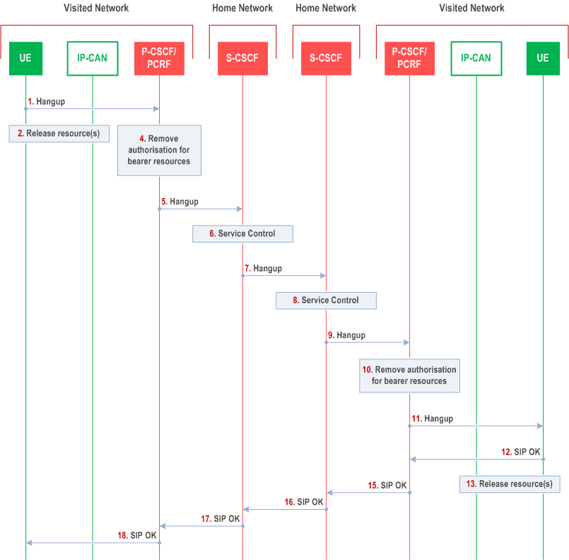
The following flow shows a terminal initiated IM CN subsystem application (SIP) session release. It is assumed that the session is active and that the bearer was established directly between the two visited networks (the visited networks could be the Home network in either or both cases). Furthermore, the flow also assumes that Policy and Charging Control is in use.

Step 1.
One party hangs up, which generates a message (Bye message in SIP) from the UE to the P-CSCF.
Step 2.
Depending on the bearer establishment mode selected for the IP-CAN session, release resource(s) shall be initiated either by the UE or by the IP-CAN itself. The UE initiates the release procedures for the resources used for this session as shown in Figure 5.22. Otherwise, the IP-CAN initiates the release of used resources after step 4.
Step 3.
Void.
Step 4.
The P-CSCF instruct the PCRF/PCF to remove the authorization for resources that had previously been issued for this endpoint for this session. This step will also result in a release indication to the IP-CAN to confirm that the IP bearers associated with the session have been deleted.
Step 5.
The P-CSCF sends a Hangup to the S-CSCF of the releasing party.
Step 6.
The S-CSCF invokes whatever service logic procedures are appropriate for this ending session.
Step 7.
The S-CSCF of the releasing party forwards the Hangup to the S-CSCF of the other party.
Step 8.
The S-CSCF invokes whatever service logic procedures are appropriate for this ending session.
Step 9.
The S-CSCF of the other party forwards the Hangup on to the P-CSCF.
Step 10.
The P-CSCF instructs the PCRF/PCF to remove the authorization for resources that had previously been issued for this endpoint for this session. This step also results in a release indication to the IP-CAN to confirm that the IP bearers associated with the UE#2 session have been deleted.
Step 11.
The P-CSCF forwards the Hangup on to the UE.
Step 12.
The terminal responds with an acknowledgement, the SIP OK message (number 200), that is sent back to the P-CSCF.
Step 13.
Depending on the bearer establishment mode selected for the IP-CAN session, release resource(s) shall be initiated either by the UE or by the IP-CAN itself. The UE initiates the release procedures for the resources used for this session as shown in Figure 5.22. Otherwise, the IP-CAN initiates the release of used resources after step 11.
Step 14.
Void.
Step 15.
The SIP OK message is sent to the S-CSCF.
Step 16.
The S-CSCF of the other party forwards the OK to the S-CSCF of the releasing.
Step 17.
The S-CSCF of the releasing party forwards the OK to the P-CSCF of the releasing.
Step 18.
The P-CSCF of the releasing party forwards the OK to the UE.
5.10.2 PSTN initiated session release p. 155
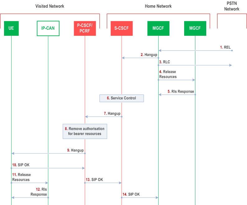
The following flow shows a PSTN terminal initiated IM CN subsystem application (SIP) session release. It is assumed that the session is active and that the bearer was established to the PSTN from the Home Network (the visited network could be the Home network in this case). Furthermore, this flow assumes that Policy and Charging Control is used.

Step 1.
PSTN party hangs up, which generates an ISUP REL message to the MGCF.
Step 2.
The MGCF sends a Hangup (Bye message in SIP) to the S-CSCF to notify the terminal that the far end party has disconnected.
Step 3.
Step 3 may be done in parallel with Step 2. Depending on the GSTN network type Step 3 may need to wait until after step 14. The MGCF notes the reception of the REL and acknowledges it with an RLC. This is consistent with the ISUP protocol.
Step 4.
The MGCF requests the MGW to release the vocoder and ISUP trunk using the H.248/MEGACO Transaction Request (subtract). This also results in disconnecting the two parties in the H.248 context. The IP network resources that were reserved for the message receive path to the PSTN for this session are now released. This is initiated from the MGW. If RSVP was used to allocated resources, then the appropriate release messages for that protocol would be invoked here.
Step 5.
The MGW sends an acknowledgement to the MGCF upon completion of step 4.
Step 6.
The S-CSCF invokes whatever service logic procedures are appropriate for this ending session.
Step 7.
The S-CSCF forwards the Hangup to the P-CSCF.
Step 8.
The P-CSCF instructs the PCRF/PCF to remove the authorization for resources that had previously been issued for this endpoint for this session. This step also results in a release indication to the IP-CAN to confirm that the IP bearers associated with the UE#2 session have been deleted.
Step 9.
The P-CSCF forwards the Hangup to the UE.
Step 10.
The terminal responds with an acknowledgement, the SIP OK message (number 200), which is sent back to the P-CSCF.
Step 11-12.
The IP network resources that had been reserved for the message receive path to the endpoint for this session are released, taking into account the bearer establishment mode used for the IP-CAN session. Steps 11 and 12 may be done in parallel with step 10. If RSVP was used to allocated resources, then the appropriate release messages for that protocol would be invoked here.
Step 13.
The SIP OK message is sent to the S-CSCF.
Step 14.
The S-CSCF forwards the message to the MGCF.
5.10.3 Network initiated session release p. 156
5.10.3.0 Removal of IP-CAN bearer used to transport IMS SIP signalling p. 156
It is possible that the IP-CAN removes the IP-CAN bearer used to transport IMS SIP signalling (e.g. due to overload situations).
In this case the UE or network shall initiate a procedure to re-establish (or modify where possible) an IP-CAN bearer to transport IMS SIP signalling. After the re-establishment of an IP-CAN bearer the UE should perform a re-registration to the IMS.
If the re-establishment (or the modification) fails then the UE or network shall de-activate all other IMS related IP-CAN bearer(s).
The deactivation of the IP-CAN bearer(s) results in the P-CSCF being informed via PCRF/PCF of the IP-CAN bearer release P-CSCF may, depending on policy, initiate a network initiated session release as described in clause 5.10.3.1.
The failure in re-establishing the ability to communicate towards the UE results also in the P-CSCF/PCRF/PCF being informed that the IMS SIP signalling transport to the UE is no longer possible which shall lead to a network initiated session release (initiated by the P-CSCF) as described in clause 5.10.3.1 if any IMS related session is still ongoing for that UE. Additionally, the P-CSCF shall reject subsequent incoming session requests towards the remote endpoint indicating that the user is not reachable, until either:
- the registration timer expires in P-CSCF and the user is de-registered from IMS.
- a new Register message from the UE is received providing an indication to the P-CSCF that the IMS SIP signalling transport for that user has become available again and session requests can be handled again.
5.10.3.1 Network initiated session release - P-CSCF initiated p. 156
5.10.3.1.0 General |R6| p. 156
This clause assumes that Policy and Charging Control is applied
The following flows show a Network initiated IM CN subsystem application (SIP) session release. It is assumed that the session is active and that the bearer was established directly between the two visited networks (the visited networks could be the Home network in either or both cases).
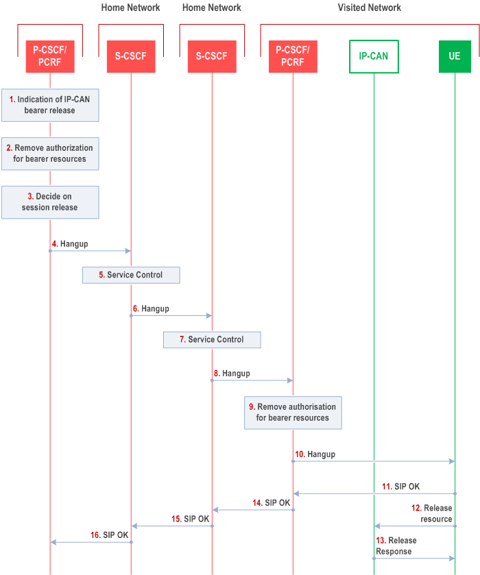
A bearer is removed e.g. triggered by a UE power down, due to a previous loss of coverage, or accidental/malicious removal, etc. In this case an IP-CAN session modification procedure (GW initiated) will be performed (see TS 23.203 and TS 23.503). The flow for this case is shown in Figure 5.26.
Other network initiated session release scenarios are of course possible.
5.10.3.1.1 Network initiated session release - P-CSCF initiated - after removal of IP-Connectivity Access Network bearer p. 157

Step 1.
The following steps are only performed if the P-CSCF has decided to terminate the session.
A bearer related to the session is terminated. The P-CSCF receives an indication via PCRF/PCF of IP-CAN bearer release.
Step 2.
The P-CSCF instructs PCRF/PCF to remove the authorization for resources related to the released bearer that had previously been issued for this endpoint for this session (see TS 23.203 and TS 23.503). It is optional for the P-CSCF to instruct PCRF/PCF to deactivate additional IP-CAN bearers (e.g. an IP-CAN bearer for chat could still be allowed).
Step 3.
The P-CSCF decides on the termination of the session. For example, the P-CSCF may decide to terminate the session if all IP-CAN bearers related to the same IMS session are deleted. In the event of the notification that the signalling transport to the UE is no longer possible, the P-CSCF shall terminate any ongoing session with that specific UE.
If the P-CSCF decides to terminate the session, then the P-CSCF instructs the PCRF/PCF to remove the authorization for resources that has previously been issued for this endpoint for this session (see TS 23.203 and TS 23.503).
Step 4.
The P-CSCF generates a Hangup (Bye message in SIP) to the S-CSCF of the releasing party.
Step 5.
The S-CSCF invokes whatever service logic procedures are appropriate for this ending session.
Step 6.
The S-CSCF of the releasing party forwards the Hangup to the S-CSCF of the other party.
Step 7.
The S-CSCF invokes whatever service logic procedures are appropriate for this ending session.
Step 8.
The S-CSCF of the other party forwards the Hangup on to the P-CSCF.
Step 9.
The P-CSCF instructs the PCRF/PCF to remove the authorization for resources that had previously been issued for this endpoint for this session. This step also results in a release indication to the IP-CAN to confirm that the IP bearers associated with the session have been deleted for UE#2.
Step 10.
The P-CSCF forwards the Hangup on to the UE.
Step 11.
The UE responds with an acknowledgement, the SIP OK message (number 200), which is sent back to the P-CSCF.
Step 12-13.
Steps 12 and 13 may be done in parallel with step 11. The IP network resources that had been reserved for the UE for this session are released, taking into account the bearer establishment mode used for the IP-CAN session. If RSVP was used to allocated resources, then the appropriate release messages for that protocol would be invoked here.
Step 14.
The SIP OK message is sent to the S-CSCF.
Step 15.
The S-CSCF of the other party forwards the OK to the S-CSCF of the releasing party.
Step 16.
The S-CSCF of the releasing party forwards the OK to the P-CSCF of the releasing party.
5.10.3.1.2 Void
5.10.3.2 Network initiated session release - S-CSCF Initiated p. 158
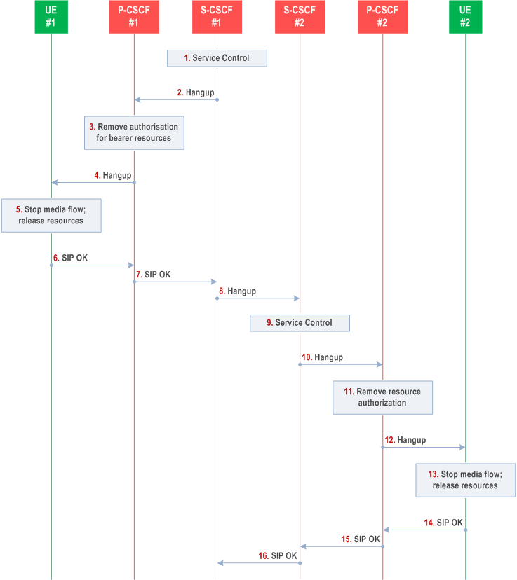
The following flow shows a network-initiated IM CN subsystem application session release, where the release is initiated by the S-CSCF. This can occur in various service scenarios, e.g. administrative, or prepaid.
The procedures for clearing a session, when initiated by an S-CSCF, are as shown in the following information flow. The flow assumes that Policy and Charging Control is in use.

Information flow procedures are as follows:
Step 1.
S-CSCF#1 decides the session should be terminated, due to administrative reasons or due to service expiration.
Step 2.
S-CSCF#1 sends a Hangup message to P-CSCF#1
Step 3.
P-CSCF#1 removes the authorization for resources that had previously been issued for this endpoint for this session. This step also results in a release indication to the IP-CAN to confirm that the IP bearers associated with the session have been deleted for UE#1.
Step 4.
P-CSCF#1 forwards the Hangup message to UE#1.
Step 5.
UE#1 stops sending the media stream to the remote endpoint, and the resources used for the session are released taking into account the bearer establishment mode used for the IP-CAN session.
Step 6.
UE#1 responds with a SIP-OK message to its proxy, P-CSCF#1.
Step 7.
P-CSCF#1 forwards the SIP-OK message to S-CSCF#1.
Step 8.
S-CSCF#1 sends a Hangup message to S-CSCF#2. This is done at the same time as flow#2
Step 9.
S-CSCF#2 invokes whatever service logic procedures are appropriate for this ending session.
Step 10.
S-CSCF#2 forwards the Hangup message to P-CSCF#2.
Step 11.
P-CSCF#2 removes the authorization for resources that had previously been issued for this endpoint for this session. This step also results in a release indication to the IP-CAN to confirm that the IP bearers associated with the session have been deleted for UE#2.
Step 12.
P-CSCF#2 forwards the Hangup message to UE#2.
Step 13.
UE#2 stops sending the media stream to the remote end point, and the resources used for the session are released taking into account the bearer establishment mode used for the IP-CAN session.
Step 14.
UE#2 acknowledges receipt of the Hangup message with a SIP-OK final response, send to P-CSCF#2.
Step 15.
P-CSCF#2 forwards the SIP-OK final response to S-CSCF#2.
Step 16.
S-CSCF#2 forwards the SIP-OK final response to S-CSCF#1.