Content for TS 23.228 Word version: 19.1.0
1…
3…
4…
4.2.4…
4.3…
4.4…
4.13…
4.16…
5…
5.2…
5.3…
5.4…
5.4.7…
5.4.8…
5.4a…
5.5…
5.5.3…
5.6…
5.6.3…
5.7…
5.7.3…
5.7.5…
5.7.8…
5.8…
5.10…
5.11…
5.11.3…
5.11.3.3
5.11.3.4
5.11.4…
5.11.5…
5.11.5.3…
5.11.6…
5.12…
5.16…
5.16.2…
5.19…
5.20…
A…
E…
E.2.2…
G…
G.5…
H
I…
J…
K…
L…
M…
M.3…
N…
P…
Q…
Q.2.5…
R…
S…
T…
U…
U.2…
V…
W…
X…
Y…
Z…
AA…
AA.3…
AB…
AC…
AC.7…
AC.7.2…
AC.7.2.2
AC.7.2.3…
AC.7.4…
AC.7.9…
AC.7.9.3…
AC.7.10…
AC.7.10.4.2…
AC.9…
AC.10…
AC.11…
AD…
AE…
AF…
AG…
G.5 Network elements for employing NAT Traversal for ICE and Outbound
G.5.1 General requirements
G.5.2 ICE
G.5.2.1 Overview
G.5.2.2 Required functions of the UE
G.5.2.3 Required functions of the STUN relay server
G.5.2.4 Required functions of the STUN server
G.5.3 Outbound
G.5.3.1 Overview
G.5.3.2 Required functions of the P-CSCF
G.5.3.3 Required functions of the S-CSCF
G.5.3.4 Required functions of the UE
G.6 Procedures for employing ICE and Outbound
G.6.1 Flow establishment procedures
G.6.2 Session establishment procedures
G.6.3 Session release procedures
G.6.4 Session modification procedures
G.6.5 Policy and Charging Control procedures
G.6.6 Detection of NAT Traversal support
G.6.7 Procedures at other IMS entities processing SDP
...
...
G.5 Network elements for employing NAT Traversal for ICE and Outbound p. 240
G.5.1 General requirements p. 240
In addition to the general requirements outline in clause G.1.1, the following NAT traversal solution also addresses the following additional requirements:
- Does not require the network to be aware of the presence of a NAT;
- Avoid unnecessarily long media paths due to media pinning;
- It shall be possible to establish communication towards a remote UE that does not support of the functionality listed in clause G.5;
- Minimize the impacts on Policy and Charging Control functionality.
G.5.2 ICE p. 240
G.5.2.1 Overview p. 240
The Interactive Connectivity Establishment (ICE) described in RFC 5245 defines a methodology for media traversal of NAT devices.
However, ICE is not a complete solution in of itself as ICE only addresses address advertisement and NAT binding maintenance. ICE does not address RTP and RTCP port symmetry requirements or non-sequential RTP and RTCP port assignment. A complete UE managed NAT traversal solution shall take into account each of these issues.
G.5.2.2 Required functions of the UE p. 241
When supporting ICE, the UE is responsible for managing the overall NAT traversal process and for invoking the various protocol mechanisms to implement the NAT traversal approach. As such, the following functions shall be performed by the UE:
- STUN relay server and STUN server discovery;
- Transmission of media packets from the same port on which it expects to receive media packets;
- RTCP port advertisement.
-
ICE functionality which includes:
- Maintaining of NAT bindings to insure inbound media packets are allowed to traverse the NAT device.
-
Address advertisement, which consists of the following operations:
- Gathering candidate addresses for media communications;
- Advertising the candidate addresses in a special SDP attribute (a=candidate) along with the active transport address in the m/c lines of the SDP.
- Perform connectivity checks on the candidate addresses in order to select a suitable address for communications.
- STUN relay server assigned address;
- STUN derived address;
- Locally assigned address.
G.5.2.3 Required functions of the STUN relay server p. 241
The STUN relay server and associated signalling requirements are documented in RFC 5766 and its use is detailed in RFC 5245. No additional requirements are placed on this server.
G.5.2.4 Required functions of the STUN server p. 241
G.5.3 Outbound p. 242
G.5.3.1 Overview p. 242
RFC 5626 "Managing Client-Initiated Connections in the Session Initiation Protocol" (Outbound) defines a methodology for signalling traversal of NAT devices. This methodology involves the establishment of flows to allow for the routing of inbound dialog initiating requests and the maintenance of the flow through keep-alive messages. Outbound does not however address inbound response routing or inbound mid-dialog requests. A complete UE managed NAT traversal solution shall take into account each of these issues.
This clause is restricted to the use of Outbound in the context of SIP NAT traversal and not to the usage of Outbound for multiple registration support.
G.5.3.2 Required functions of the P-CSCF p. 242
When supporting Outbound, the P-CSCF's primary role in NAT traversal is to ensure that requests and responses occur across a flow for which there is an existing NAT binding. The P-CSCF shall ensure that inbound dialog initiating requests can be forwarded to the UE on a flow for which there is an existing NAT binding.
The P-CSCF shall ensure that all responses to the UE including those from mid-dialog requests are sent to the same source IP address and port which the request was received from.
The P-CSCF shall also implement a limited STUN server functionality to support the STUN keep-alive usage as defined in RFC 5389 which is used by the UE to maintain the NAT bindings.
Additionally the P-CSCF shall transmit signalling packets from the same port on which it expects to receive signalling packets.
G.5.3.3 Required functions of the S-CSCF p. 242
When supporting Outbound, the S-CSCF should be responsible for indicating to the UE that Outbound procedures are supported.
G.5.3.4 Required functions of the UE p. 242
When supporting Outbound, the UE is responsible for managing the overall NAT traversal process and for invoking the various protocol mechanisms to implement the NAT traversal approach. As such, the following functions shall be performed by the UE:
- Maintaining of NAT bindings between the UE and the P-CSCF through the use of a keep-alive mechanism to insure inbound signalling packets are allowed to traverse the NAT device.
- Transmission of signalling packets from the same port on which it expects to receive signalling packets;
- Establishment of signalling flows to its assigned P-CSCF(s) during registration.
G.6 Procedures for employing ICE and Outbound p. 243
The procedures described in the following clauses are applied in addition to the procedures of the UE and P-CSCF described in other clauses of this specification.
G.6.1 Flow establishment procedures p. 243
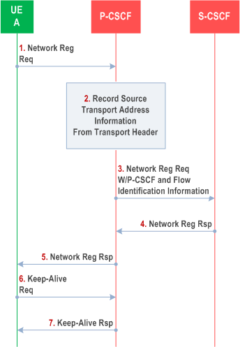
This procedure is initiated by the UE at network registration time, and allows for the establishment of a flow between a UE and its assigned P-CSCF. This flow can then be used by the P-CSCF to allow an initial inbound request to traverse the NAT.

Step 1.
UE-A initiates network registration by sending a registration request to its assigned P-CSCF.
Step 2.
Upon receipt of a registration request, the P-CSCF stores received transport header. This includes information to identify the flow between P-CSCF and UE.
Step 3.
The P-CSCF then sends the registration request to the assigned S-CSCF after adding information identifying the serving P-CSCF to the registration request.
Step 4.
The S-CSCF stores the information identifying the serving P-CSCF and returns a registration response.
Step 5.
Upon receipt of the registration responses from the S-CSCF, the P-CSCF forwards the registration response to UE-A using the stored transport address information from the registration request.
Step 6.
UE-A sends a Keep-Alive request to its assigned P-CSCF using the same transport address information (source and destination) which was used for the registration request. This Keep-Alive ensures that a NAT binding exists between UE-A and the P-CSCF allowing for inbound session requests from the P-CSCF to UE-A.
Step 7.
The P-CSCF responds with a Keep-Alive response which also reflects the received source transport address information. Inclusion of such information allows UE-A to determine if the NAT has rebooted and assigned a new binding and take appropriate action.
G.6.2 Session establishment procedures p. 244
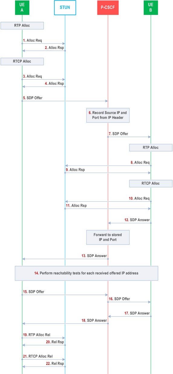
The following procedure illustrates the session establishment procedures when both UEs support the ICE methodology. These procedures apply to both the terminating and originating side of the session regardless of whether the UE is behind a NAT.
In the following Figure the STUN element represents both a STUN server and STUN Relay server as a single logical element. It would be equally valid if these functions we represented in separate logical elements. The procedures are unaffected by the grouping. Further, this call flow represents a simplified view to illustrate the NAT traversal procedures only. Other network elements not show may be involved in the session establishment process.

Step 1.
UE-A begins candidate transport address collection by performing a request for a transport address for each media flow from the STUN server.
Step 2.
The STUN server reserves one of its transport addresses for each media flow and sends the reserved transport address information back to the UE. The STUN server also reflects the source transport address of the original request for a transport address.
If the UE fails to identify STUN servers it concludes that ICE and Outbound procedures are not supported by the network and defaults to operation using the procedures described in clause G.4.
Step 3-4.
UE-A repeats the procedures for requesting a transport address for each RTCP flow. These steps may be executed in parallel with steps 1. - 2. or in series.
Step 5.
With its three candidates (locally assigned, server reflected and relay) UE-A forms an offer and forwards to its assigned P-CSCF. The UE includes the SP cand-type, SP rel-addr and SP rel-port in the candidate attribute as defined in RFC 5245.
Step 6.
To ensure subsequent responses to the offer are allowed through the NAT, the P-CSCF stores the transport address information received in the transport header of the offer.
Step 7.
The P-CSCF forwards the Offer to UE-B using one of the previously established flows.
Step 8-11.
UE-B performs the candidate gathering procedures as outlined in steps 1. - 4. above.
Step 12.
With its three candidates (locally assigned, server reflected and relay) UE-B forms an answer and forwards to its assigned P-CSCF.
Step 13.
The P-CSCF for UE-A forwards the Answer to UE-A based on the previously stored transport address information. Media can being to flow at this point using the default transport addresses (recommended to be the STUN Relay provided address).
Step 14.
Both UE-A and UE-B perform connectivity tests on each received transport address to determine which of the received transport addresses are actually reachable.
Step 15.
After the connectivity tests are concluded UE-A sends an updated SDP Offer indicating the agreed to transport address.
Step 16.
The P-CSCF forwards the Offer according to normal routing procedures.
Step 17.
UE-B sends an Answer indicating the agreed to transport address.
Step 18.
The P-CSCF forwards the Answer according to normal routing procedures. Media can begin flowing using the newly identified addresses.
Step 19-21.
STUN Relay allocated transport addresses are released by the UE once a more efficient address has been identified and the session updated.
G.6.3 Session release procedures p. 246
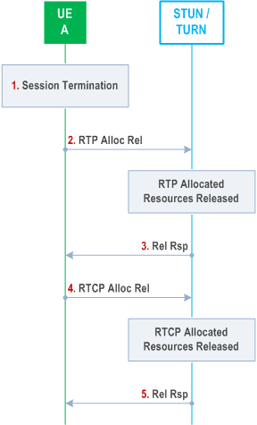
This procedure is applied to by the UE if the IMS-ALG function is not supported by the network, but the network does support ICE and Outbound procedures. Normal session release procedures are followed with the following exception. If a STUN Relay allocated transport address was used for the session, it shall be released by the UE for which the transport address was allocated.
In the following Figure the STUN element represents both a STUN server and STUN Relay server as a single logical element. It would be equally valid if these functions we represented in separate logical elements. The procedures are unaffected by the grouping.

Step 1.
UE-A receives a trigger to release the session for which STUN Relay resources were allocated.
Step 2.
UE-A sends an indication to the STUN Relay server to release resources allowed for RTP.
Step 3.
The STUN Relay server releases the allocated resources and returns a response.
Step 4.
UE-A sends an indication to the STUN Relay server to release resources allowed for RTCP.
Step 5.
The STUN Relay server releases the allocated resources and returns a response.
G.6.4 Session modification procedures p. 247
A session modification can cause the creation, and/or modification, and/or release of media flows.
This procedure is applied to by the UE if the IMS-ALG function is not supported by the network, but the network does support ICE and Outbound procedures. When a new media flow is created the procedure used during session establishment for updating the transport addresses (steps 15-17. of the session establishment procedures) shall be applied.
When an existing media flow is released the procedure for session termination shall be applied for the particular media flow.
When an existing media flow is modified, this may lead to a modification of the media flow directly, or to the establishment of a new media flow and release of the existing one.
G.6.5 Policy and Charging Control procedures p. 247
When PCC is to be employed for a session, the P-CSCF is responsible for providing the PCRF/PCF with IMS media flow information related to the service. If the UE has indicated that the active transport address corresponds to a relayed address, the P-CSCF shall be responsible for using the additional information provided by the UE to convert the media flows derived from the SDP into flow descriptions which will traverse the Policy and Charging Enforcement Point.
The deployment of STUN relay servers requires that the UE be able to communicate with such servers prior to session establishment. The PCC for the IP-CAN must be set up to allow communication with the STUN relay server prior to IMS session establishment. This may impact gating control in some IP-CANs which do not support a default or best effort flow which can be used to communicate with the STUN relay server prior to session establishment.
G.6.6 Detection of NAT Traversal support p. 248
The UE shall be able to determine whether the IMS CN supports the Outbound procedures by the capabilities indicated in the registration response to the UE. If the indication of the capability is present, the UE knows that the IMS CN supports Outbound and the associated procedures.
G.6.7 Procedures at other IMS entities processing SDP p. 248
IMS entities processing SDP, such as the P-CSCF, IBCF or MRFs, may or may not be updated to understand the "candidate alternative addresses" that are part of the ICE procedures, RFC 5245. IMS entities processing SDP that do not understand the ICE procedures will, in accordance with there compatibility procedures, ignore the "alternative addresses", and media entities, such as the IMS Access Gateway, PCEF, MRFP and TrGW, controlled by the IMS entities processing SDP will not pass connectivity check requests and media on those addresses. IMS entities processing SDP which behave as B2BUAs may or may not pass on the alternative address in accordance with their own compatibility procedures.