Content for TS 23.228 Word version: 19.1.0
1…
3…
4…
4.2.4…
4.3…
4.4…
4.13…
4.16…
5…
5.2…
5.3…
5.4…
5.4.7…
5.4.8…
5.4a…
5.5…
5.5.3…
5.6…
5.6.3…
5.7…
5.7.3…
5.7.5…
5.7.8…
5.8…
5.10…
5.11…
5.11.3…
5.11.3.3
5.11.3.4
5.11.4…
5.11.5…
5.11.5.3…
5.11.6…
5.12…
5.16…
5.16.2…
5.19…
5.20…
A…
E…
E.2.2…
G…
G.5…
H
I…
J…
K…
L…
M…
M.3…
N…
P…
Q…
Q.2.5…
R…
S…
T…
U…
U.2…
V…
W…
X…
Y…
Z…
AA…
AA.3…
AB…
AC…
AC.7…
AC.7.2…
AC.7.2.2
AC.7.2.3…
AC.7.4…
AC.7.9…
AC.7.9.3…
AC.7.10…
AC.7.10.4.2…
AC.9…
AC.10…
AC.11…
AD…
AE…
AF…
AG…
5.7.8 (AST#4) Termination at Application Server based on service logic
5.7a Procedures for the establishment of sessions without preconditions
5.7a.1 General
5.7a.2 Procedures for the establishment of sessions without preconditions - no resource reservation required before session becomes active
...
...
5.7.8 (AST#4) Termination at Application Server based on service logic |R6| p. 144
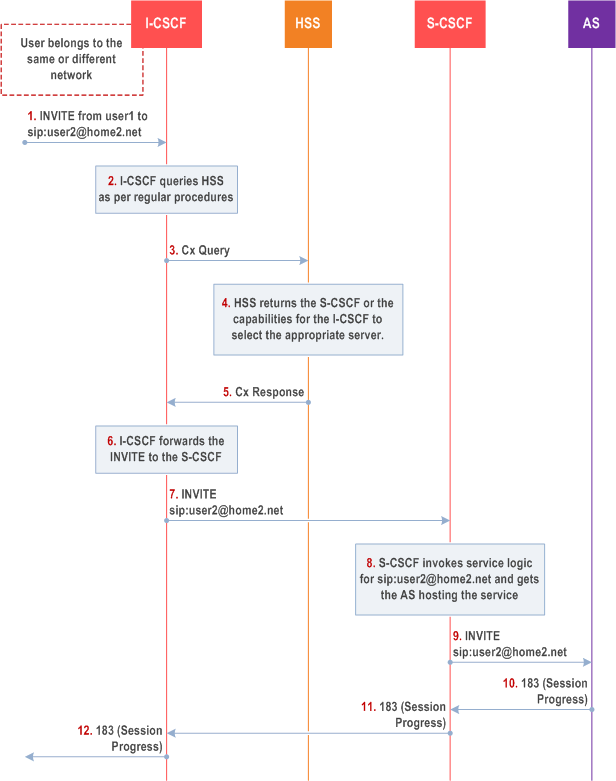
This termination procedure applies to an Application Server that terminates a session. In this case the addressed user is a UE and is not hosted by the AS. Based on the invoked service logic at the Application Server the session is terminated at the AS.
The procedure described below assumes that the Application Server takes care of the user plane connection.

Step 1.
I-CSCF receives a request destined to the user.
Step 2-3.
I-CSCF queries HSS in order to determine the next hop in the routing path for the user.
Step 4.
HSS determines the routing information, which is the S-CSCF defined for the user.
Step 5.
HSS returns the S-CSCF address/capabilities to the I-CSCF.
Step 6-7.
I-CSCF, as per existing procedures, forwards the request to S-CSCF that will handle the session termination.
Step 8.
S-CSCF evaluates the filter criteria and gets the AS address where to forward the request.
Step 9.
The request is then routed towards the AS identified by the filter criteria. The AS terminates the session instead of allowing it to continue on to the address end user.
Step 10-12.
Session setup continues as per existing procedures.
5.7a Procedures for the establishment of sessions without preconditions |R6| p. 145
5.7a.1 General p. 145
These clauses present the general end-to-end session flow procedures without preconditions. The flow in clause 5.7a.2 is applicable to services without real-time QoS requirements before session becomes active, and thus do not need to set-up dedicated IP-CAN bearers but can use existing IP-CAN bearers, and to services which do not require that the terminating endpoint obtains a SIP-level notification when the originating endpoint's IP-CAN bearer becomes available.
Note that the flows in these clauses do not show the use of a THIG. If a THIG is used, the use is completely analogous to the use in clause 5.5, clause 5.6 and clause 5.7.
5.7a.2 Procedures for the establishment of sessions without preconditions - no resource reservation required before session becomes active p. 147

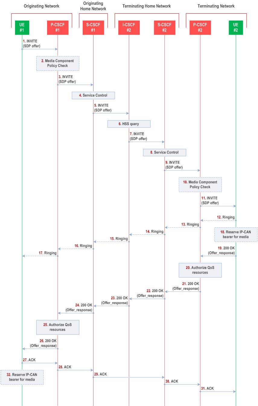
Step 1.
UE#1 sends the SIP INVITE request, containing an initial SDP, to the P-CSCF#1 determined via the P-CSCF discovery mechanism. The initial SDP may represent one or more media for a multi-media session. It should be noted that a media offer without preconditions in general implies that the offering entity might expect to receive incoming media for any of the offered media as soon as the offer is received by the other endpoint. Therefore either an existing IP-CAN bearer is assumed to be available for use or the application is implemented such that incoming media is not expected until some later point in time.
Step 2.
P-CSCF#1 examines the media parameters. If P-CSCF#1 finds media parameters not allowed to be used within an IMS session (based on P-CSCF local policies, or if available bandwidth authorization limitation information coming from the PCRF/PCF), it rejects the session initiation attempt.
Step 3.
P-CSCF#1 forwards the INVITE request to S-CSCF#1 along the path determined upon UE#1's most recent registration procedure.
Step 4.
Based on operator policy S-CSCF#1 validates the user's service profile and may invoke whatever service control logic is appropriate for this INVITE request. This may include routing the INVITE request to an Application Server, which processes the request further on.
Step 5.
S-CSCF#1 forwards INVITE request to I-CSCF#2.
Step 6.
I-CSCF#2 performs Location Query procedure with the HSS to acquire the S-CSCF address of the destination user (S-CSCF#2).
Step 7.
I-CSCF#2 forwards the INVITE request to S-CSCF#2.
Step 8.
Based on operator policy S-CSCF#2 validates the user's service profile and may invoke whatever service control logic is appropriate for this INVITE request. This may include routing the INVITE request to an Application Server, which processes the request further on.
Step 9.
S-CSCF#2 forwards the INVITE request to P-CSCF#2 along the path determined upon UE#2's most recent registration procedure.
Step 10.
P-CSCF#2 examines the media parameters. If P-CSCF#2 finds media parameters not allowed to be used within an IMS session (based on P-CSCF local policies, or if available bandwidth authorization limitation information coming from the PCRF/PCF), it rejects the session initiation attempt.
Step 11.
P-CSCF#2 forwards the INVITE request to UE#2.
Step 12. - 17.
UE#2 may optionally generate a ringing message towards UE#1.
Step 18.
Depending on the bearer establishment mode selected for the IP-CAN session, resource reservation shall be initiated either by the UE or by the IP-CAN itself. UE#2 may reserve a dedicated IP-CAN bearer for media based on the media parameters received in the SDP offer as shown in Figure 5.19h. Otherwise, the IP-CAN#2 initiates the reservation of required resources after step 20 instead.
Step 19.
UE#2 accepts the session with a 200 OK response. The 200 OK response is sent to P-CSCF#2.
Step 20.
Based on operator policy P-CSCF#2 may instruct PCRF/PCF to authorize the resources necessary for this session.
Step 21. - 24.
The 200 OK response traverses back to UE#1.
Step 25.
Based on operator policy P-CSCF#1 may instruct the PCRF/PCF to authorize the resources necessary for this session.
Step 26.
P-CSCF#1 forwards the 200 OK response to UE#1.
Step 27. - 31.
UE#1 acknowledges the 200 OK with an ACK, which traverses back to UE#2.
Step 32.
Depending on the bearer establishment mode selected for the IP-CAN session, resource reservation shall be initiated either by the UE or by the IP-CAN itself. UE#1 may reserve a dedicated IP-CAN bearer for media based on the media parameters received in the SDP answer as shown in Figure 5.19h. Otherwise, the IP-CAN#1 initiates the reservation of required resources after step 25.