Content for TS 23.228 Word version: 19.1.0
1…
3…
4…
4.2.4…
4.3…
4.4…
4.13…
4.16…
5…
5.2…
5.3…
5.4…
5.4.7…
5.4.8…
5.4a…
5.5…
5.5.3…
5.6…
5.6.3…
5.7…
5.7.3…
5.7.5…
5.7.8…
5.8…
5.10…
5.11…
5.11.3…
5.11.3.3
5.11.3.4
5.11.4…
5.11.5…
5.11.5.3…
5.11.6…
5.12…
5.16…
5.16.2…
5.19…
5.20…
A…
E…
E.2.2…
G…
G.5…
H
I…
J…
K…
L…
M…
M.3…
N…
P…
Q…
Q.2.5…
R…
S…
T…
U…
U.2…
V…
W…
X…
Y…
Z…
AA…
AA.3…
AB…
AC…
AC.7…
AC.7.2…
AC.7.2.2
AC.7.2.3…
AC.7.4…
AC.7.9…
AC.7.9.3…
AC.7.10…
AC.7.10.4.2…
AC.9…
AC.10…
AC.11…
AD…
AE…
AF…
AG…
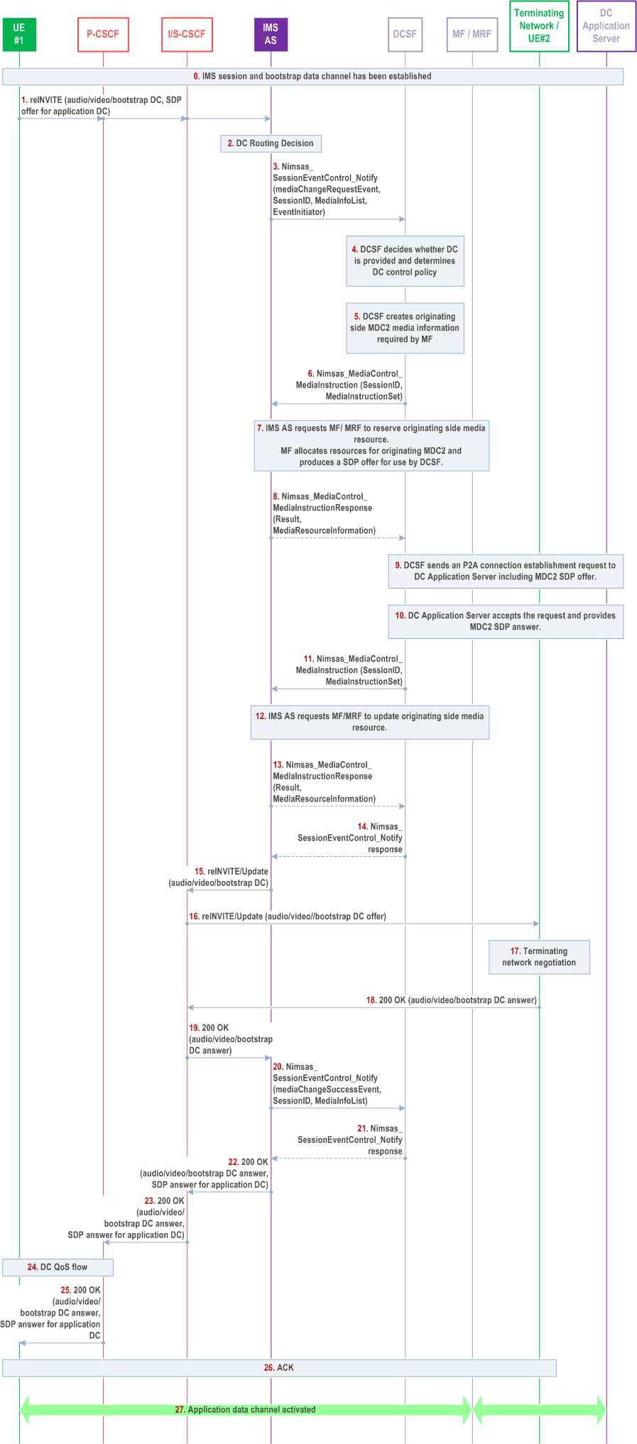
AC.7.2.2 Person-to-Application (P2A) Application Data Channel Setup p. 385
Figure AC.7.2.2-1 depicts a signalling flow diagram for establishing an Application Data Channel in a person to application use case.

The steps in the call flow are as follows:
Step 0-3.
Steps 0-3 of clause AC.7.2.1 applies.
Step 4.
After receiving the session event notification, the DCSF determines the policy about how to process the application data channel establishment request based on the related parameters (i.e. associated DC application binding information) in the notification and/or DCSF service specific policy.
Step 5.
The DCSF determines that the added Application Data Channel media of the offer takes DC Application Server as target endpoint and requires to anchor in the MF.
Step 6.
The DCSF invokes Nimsas_MediaControl service operation to instruct IMS AS to terminate the media flow of the originating UE to MF. The instruction also includes information to be consumed by the MF that the data channel media shall be relayed via the MDC2 interface.
Step 7.
The IMS AS invokes Nmf_MRM_Create (List of Media Termination Descriptors) service operation to instruct MF on application data channel establishment and data channel media resource reservation based on the DC media information received from DCSF.
Step 8.
The IMS AS notifies the MediaControl instruction control response to DCSF.
Step 9.
The DCSF stores the media resource information and sends a P2A application data channel establishment request (including the MDC2 media resource received from MF) to the DC Application Server via DC3/DC4.
Step 10.
DC Application Server accepts the P2A application data channel establishment request, returning an MDC2 reserved media resource as answer and is prepared for UE#1 traffic through MDC2.
Step 11.
DCSF requests IMS AS to update the MF resource with MDC2 media endpoint information of DC Application Server.
Step 12.
IMS AS updates the MF resource.
Step 13.
IMS AS notifies the MediaControl instruction control response to DCSF.
Step 14.
DCSF replies to the notification received in step 13.
Step 15-16.
IMS AS sends the re-INVITE to remote network side and UE#2, via the originating S-CSCF, which does not include application data channel request in the SDP for the application data channel.
Step 17-19.
UE#2 and terminating network returns a 200 OK response with SDP answer for audio/video.
Step 20.
IMS AS notifies the DCSF about the successful result of the MediaChangeRequest event.
Step 21.
DCSF replies to the notification.
Step 22-23.
The IMS AS includes SDP answer for application data channels to UE#1 in 200 OK response and sends 200 OK response to S-CSCF and P-CSCF.
Step 24.
The originating network P-CSCF executes QoS procedure for application data channel media based on the SDP answer information from the 200 OK response.
Step 25.
CSCF returns the 200 OK response to UE#1.
Step 26.
UE#1 send ACK to the terminating network.
Step 27.
The application data channel between UE#1 and DC Application Server is established via MF. MF forwards data channel traffic between UE#1 and DC Application Server based on MDC2 media point information received in step 9 and 12.