Content for TS 23.228 Word version: 19.1.0
1…
3…
4…
4.2.4…
4.3…
4.4…
4.13…
4.16…
5…
5.2…
5.3…
5.4…
5.4.7…
5.4.8…
5.4a…
5.5…
5.5.3…
5.6…
5.6.3…
5.7…
5.7.3…
5.7.5…
5.7.8…
5.8…
5.10…
5.11…
5.11.3…
5.11.3.3
5.11.3.4
5.11.4…
5.11.5…
5.11.5.3…
5.11.6…
5.12…
5.16…
5.16.2…
5.19…
5.20…
A…
E…
E.2.2…
G…
G.5…
H
I…
J…
K…
L…
M…
M.3…
N…
P…
Q…
Q.2.5…
R…
S…
T…
U…
U.2…
V…
W…
X…
Y…
Z…
AA…
AA.3…
AB…
AC…
AC.7…
AC.7.2…
AC.7.2.2
AC.7.2.3…
AC.7.4…
AC.7.9…
AC.7.9.3…
AC.7.10…
AC.7.10.4.2…
AC.9…
AC.10…
AC.11…
AD…
AE…
AF…
AG…
AC.7.9 IMS data channel setup Signalling Procedure for interworking with MTSI UE
AC.7.9.0 General
AC.7.9.1 Bootstrap Data Channel Setup Signalling Procedure
AC.7.9.2 Signalling Procedure of Application Data Channel Interworking via MF
...
...
AC.7.9 IMS data channel setup Signalling Procedure for interworking with MTSI UE |R19| p. 391
AC.7.9.0 General p. 391
defined in TS 26.114.
When the originating DCMTSI UE initiates an IMS DC session to the terminating MTSI UE, a bootstrap data channel is set up between the originating DCMTSI UE and the originating network (i.e. DCSF and MF), and an MMTEL session for the other media (e.g. audio, video, the MMTEL media other than data channel) may be set up with the terminating side based on the SDP response from the terminating MTSI UE. This is described in clause AC.7.9.1.
The originating DCMTSI UE may initiate an application data channel setup which is associated with the MMTEL session between the DCMTSI UE and the MTSI UE (e.g. for real-time screen sharing). The data channel media sent from the originating DCMTSI UE is transcoded to MMTEL media and transcoded to the terminating MTSI UE via the associated RTP stream, and the MMTEL media sent from the terminating MTSI UE is transcoded to data channel media and transferred to the originating DCMTSI UE via the associated application data channel stream. This is described in clause AC.7.9.2.
The DCMTSI UE may initiate application data channel setup with the DC AS for the data channel applications which is configured to support interworking with MTSI UE. The DC AS subscribes to the IMS AS to be notified any application data channel for the data channel applications that require interworking with an MTSI UE is set up. It is described in clause AC.7.9.3.
The DC AS may initiate data channel between the serving network of the DCMTSI UE and the DCMTSI UE when it requires interworking with MTSI UE. The DC AS subscribes the event to the IMS AS to be notified about the IMS session is established with the DCMTSI UE as the callee which is configured as an interworking provider (e.g. customer service centre). This is described in clause AC.7.9.4.
AC.7.9.1 Bootstrap Data Channel Setup Signalling Procedure p. 391
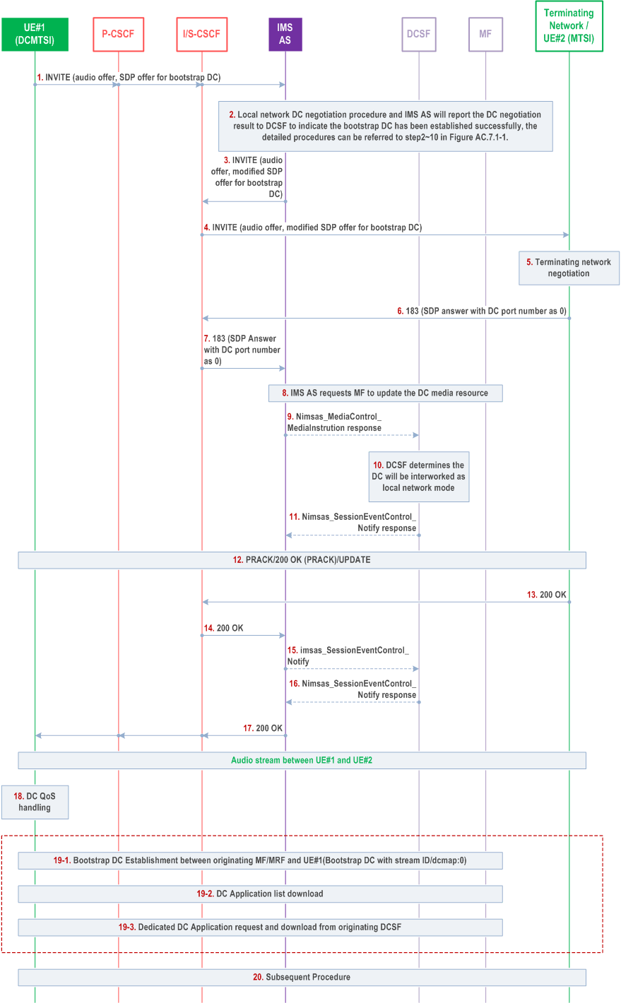
Figure AC.7.9.1-1 depicts a signalling flow diagram for establishing a bootstrap data channel when the originating DCMTSI UE initiates an IMS DC session to the terminating MTSI UE. In Figure AC.7.9.1-1, the procedure starts with the INVITE including SDP offer. The SDP offer includes for audio and data channel media and represent the minimum SDP offer to start this procedure, but it is not limited only for that media (e.g. the video offer may be included).

Step 1.
UE#1 sends the SIP INVITE request with an initial SDP to the IMS AS, through P-CSCF and S-CSCF in the originating network. The initial SDP contains SDP offers for audio and the bootstrap data channel with bootstrap DC stream ID.
Step 2.
Data channel management procedure in originating network is executed as per step2~10 in Figure AC.7.1-1.
Step 3-4.
IMS AS sends the INVITE request to remote network with SDP containing data channel media for terminating network and UE #2.
Step 5-7.
UE#2 and terminating network returns bootstrap DC negotiation result to originating network. The port number of bootstrap data channel in the SDP answer is set to zero implying that the terminating UE #2 does not support IMD DC or is not accepting the establishment of bootstrap data channel.
Step 8.
IMS AS requests MF to update the local DC media resources accordingly.
Step 9-11.
When IMS AS sends the bootstrap DC negotiation result to DCSF, since the port of bootstrap data channel for UE #2 is set to zero, the DCSF knows that the terminating network or UE #2 does not support IMS DC or does not want to use IMS data channel in this session.
Step 12-18.
These procedures are same as step 14~20 in Figure AC.7.1-1.
Step 19.
The bootstrap data channels have been established only between originating MF and UE#1.
Step 20.
The subsequent procedure applies.
AC.7.9.2 Signalling Procedure of Application Data Channel Interworking via MF p. 393
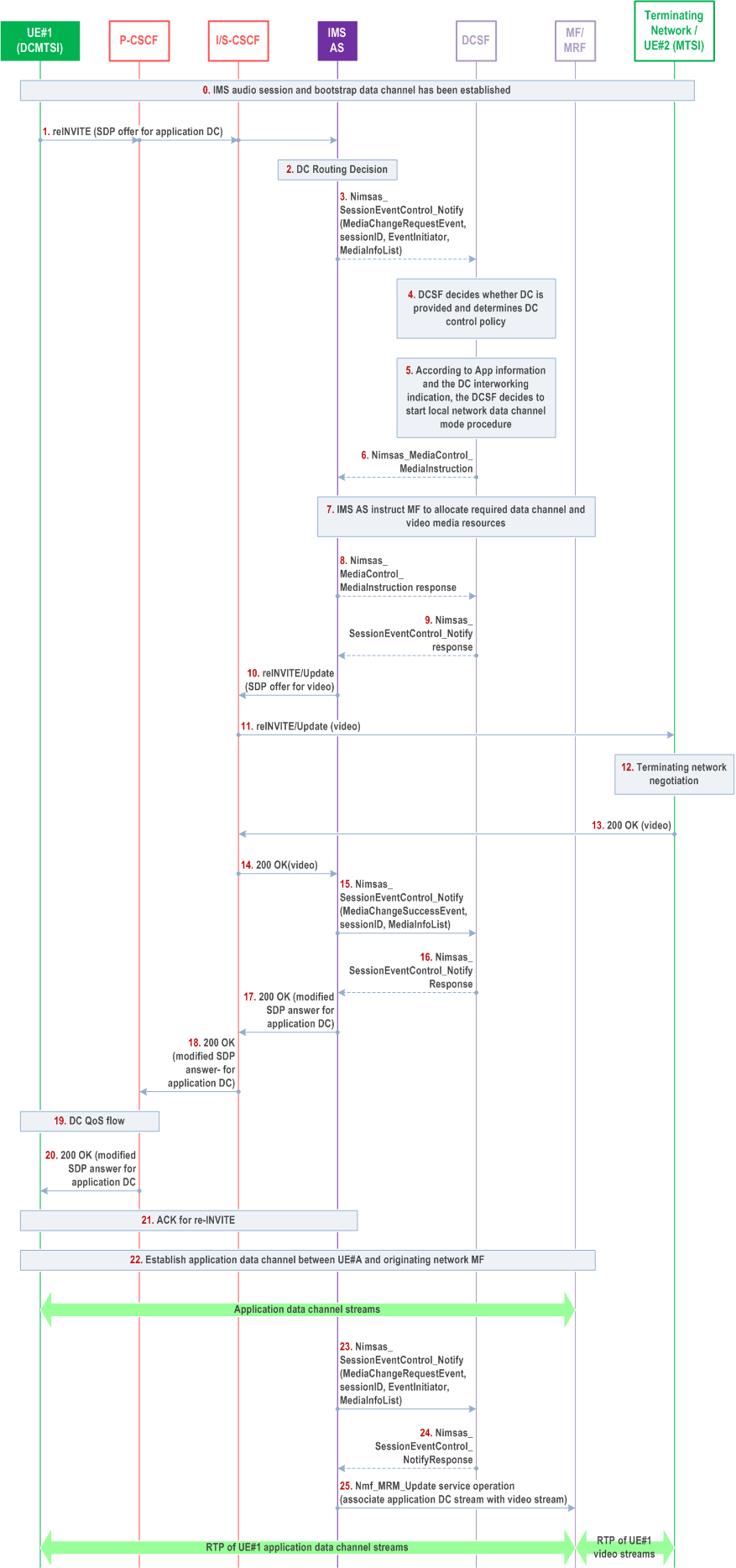
Figure AC.7.9.2-1 depicts a signalling flow diagram for establishing the application data channel when the originating DCMTSI UE initiates an IMS DC session to the terminating MTSI UE, providing interworking of application data channel to MTSI UE via MF. This signalling flow takes the data channel application which enables the transcode between the data channel media and the MMTEL media such as audio and video, e.g. Real-time Screen Sharing.

Step 1-3.
UE#1 initiates a re-INVITE request to establish an application data channel in which the application data channel and data channel application information (for instance, application ID) is included. The IMS AS validates user subscription data to determine whether this request should be notified to the DCSF as stated in clause AC.7.2.
Step 4.
After receiving the notification, the DCSF determines the policy about how to process the application data channel establishment request based on the related parameters (i.e. associated DC application binding information as application ID) in the notification and/or DCSF service specific policy.
Step 5-7.
Since the DCSF is aware that the terminating network or UE #2 does not support or does not want to use IMS data channel in this session, the DCSF determines that interworking of the application data channel media to MTSI UE is needed and possible, based on the application information, i.e. application id. The DCSF invokes Nimsas_MediaControl_MediaInstruction to the IMS AS and instructs the IMS AS to create resources and association for the application data channels on originating side and video media on terminating side. The DCSF also includes the instruction on how to transcode data channel media to video media. The IMS AS invokes Nmf_MediaResourceManagement to the MF to allocate resource and transcode data channel media to video media according to DCSF's instruction.
Step 8-9.
IMS AS responds to the MediaInstruction request received in step 6. The response may include the atomic success result of operation and also includes negotiated data channel media resource information for MDC1. The DCSF stores the media resource information and responds to the request received in step 3.
Step 10-11.
After the media resource reservation, the IMS AS sends a re-INVITE request with the SDP offer for anchoring the video media of UE#2 to the MF.
Step 12-14.
After terminating network side negotiation, UE#2 and terminating network returns 200 OK for the re-INVITE.
Step 15-16.
DCSF is notified about the terminating network media negotiation result.
Step 17-21.
The IMS AS sends 200 OK for re-INVITE initiated by UE#1 and UE#1 returns ACK.
Step 22.
UE#1 initiates SCTP association and DTLS connection establishment procedures and establishes the application data channels with the MF.
Step 23-24.
The IMS AS reports media negotiation result to the DCSF, and reports that anchoring video stream is successful. The DCSF sends a Call Control Request to the MMTel AS indicating it to continue the call process.
Step 25.
The IMS AS sends a Media Resource Management Request to the MF to associate application data channel stream between UE#1 and the MF with the allocated video streams between UE#2 and the MF.
The application data channels between the MF and UE#1 are associated with the RTP video streams between the MF and UE#2. The RTP stream of UE#1's (e.g. screenshare sequence) is received by UE#2 from video streams.