Content for TS 23.228 Word version: 19.1.0
1…
3…
4…
4.2.4…
4.3…
4.4…
4.13…
4.16…
5…
5.2…
5.3…
5.4…
5.4.7…
5.4.8…
5.4a…
5.5…
5.5.3…
5.6…
5.6.3…
5.7…
5.7.3…
5.7.5…
5.7.8…
5.8…
5.10…
5.11…
5.11.3…
5.11.3.3
5.11.3.4
5.11.4…
5.11.5…
5.11.5.3…
5.11.6…
5.12…
5.16…
5.16.2…
5.19…
5.20…
A…
E…
E.2.2…
G…
G.5…
H
I…
J…
K…
L…
M…
M.3…
N…
P…
Q…
Q.2.5…
R…
S…
T…
U…
U.2…
V…
W…
X…
Y…
Z…
AA…
AA.3…
AB…
AC…
AC.7…
AC.7.2…
AC.7.2.2
AC.7.2.3…
AC.7.4…
AC.7.9…
AC.7.9.3…
AC.7.10…
AC.7.10.4.2…
AC.9…
AC.10…
AC.11…
AD…
AE…
AF…
AG…
M IMS Local Breakout
M.1 P-CSCF located in visited network
M.1.1 Description
M.1.1.0 General
M.1.1.1 Architecture
M.1.1.2 Flow for originating session
M.2 P-CSCF located in home network
M.2.1 Description
M.2.1.0 General
M.2.1.1 Architecture
M.2.1.2 Flow for originating session
M.2.2 Address assignment
M.2.3 IPv4 - IPv6 interworking
M.2.4 NAT traversal
...
...
M IMS Local Breakout |R8| p. 267
M.1 P-CSCF located in visited network p. 267
M.1.1 Description p. 267
M.1.1.0 General |R11| p. 267
The architectures and flows in this clause are only showing EPS and 5GS. The principles shown are also applicable for GPRS Core Network.
For 5GS, there is no support for roaming interface between vPCF and hPCF in this Release of the specification.
M.1.1.1 Architecture p. 267
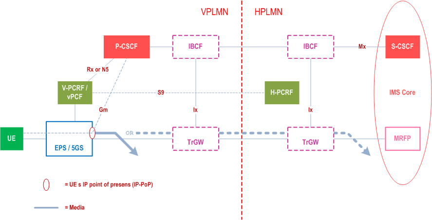
The architecture for this scenario is shown in Figure M.1.1.1.

Optionally IBCF and TrGW may be present in the HPLMN and VPLMN according to II-NNI reference architecture (see Annex K), and thus there will be an Ici reference point between the IBCFs and an Izi reference point between the TrGWs.
M.1.1.2 Flow for originating session p. 267
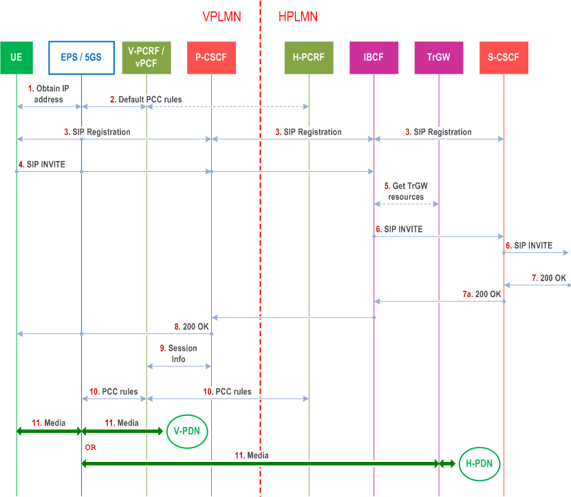
The information flows for originating session for this scenario is illustrated in Figure M.1.1.2.

Step 1.
The UE obtains an IP address from the EPS/5GS in the visited network according to the procedures specified by TS 23.401 / TS 23.502.
Step 2.
The EPS/5GS obtains default PCC rules and associates it with this IP-CAN. The V-PCRF/vPCF and H-PCRF (in the case of S9 in EPS) provides these rules according to TS 23.203 / TS 23.503.
Step 3.
Using the IP address obtained in step 1, the UE performs IMS registration. This SIP message is routed by the EPS/5GS in the visited network through the P-CSCF in the visited network, which was discovered according to the procedures in Annex E/Annex Y, to the S-CSCF in the home network, via IBCFs also in the visited and home network if deployed.
Step 4.
Using the IP address obtained in step 1 in the SDP, the UE initiates a SIP session. The INVITE request is routed by the EPS/5GS in the visited network through the P-CSCF to the IBCF in the home network.
Step 5.
If the IBCF decides to route media to home based on operator policy, it then allocates resources in TrGW and alters the offered SDP accordingly.
Step 6.
IBCF sends the INVITE further to the S-CSCF, and S-CSCF continues the session towards the far-end.
Step 7.
The 200 OK received from the far-end is sent by the S-CSCF to the IBCF. If a TrGW was allocated in step 5, then IBCF changes the SDP answer accordingly.
Step 8.
The 200 OK is sent further on to the P-CSCF and via EPS/5GS in the visited network towards the UE.
Step 9.
The P-CSCF in the visited network also provides the session information to the V-PCRF/vPCF in the visited network.
Step 10.
The H-PCRF in the home network provides PCC rules to the V-PCRF in the visited network when S9 is supported. The V-PCRF/vPCF in the visited network provisions PCC rules in the EPS/5GS in the visited network
Step 11.
Media exchanged between the UE and the far end is now routed either between the 5GS in the visited network and the far end, thus achieving local breakout mode of operation; or between the EPS/5GS in the visited network via the TrGW in the home network if IBCF was deployed.
M.2 P-CSCF located in home network p. 269
M.2.1 Description p. 269
M.2.1.0 General |R11| p. 269
The architectures and flows in this clause are only showing EPS and 5GS. The principles shown are also applicable for GPRS Core Network.
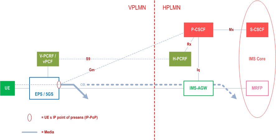
This scenario assumes that both IMS signalling and IMS media traffic are anchored in EPS/5GS in the Visited network. UE performs a P-CSCF discovery according to clause 5.1.1.0.
M.2.1.1 Architecture p. 269
The Local Breakout architecture for P-CSCF at home is shown in Figure M.2.1.1-1.

M.2.1.2 Flow for originating session p. 269
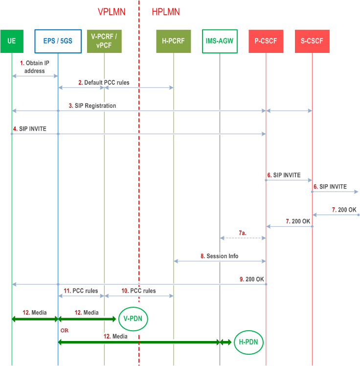
The information flows for originating session for this scenario is illustrated in Figure M.2.1.2.

Step 1.
The UE obtains an IP address from the EPS/5GS in the visited network, according to the IP Connectivity Access Network procedures specified by TS 23.401 /TS 23.502.
Step 2.
The serving EPS/5GS (in visited network) obtains default PCC rules, and associates it with this IP-CAN. The V-PCRF/vPCF and H-PCRF (in the case S9 in EPS is available) provides these rules according to TS 23.203 / TS 23.503.
Step 3.
Using the IP address obtained in step 1, the UE performs IMS registration. This SIP message is IP-routed by the EPS/5GS, in the visited network, to the P-CSCF in the home network, which was discovered according to the procedures in clause 5.1.1. When P-CSCF receives the REGISTER message, it optionally interacts with H-PCRF/vPCF to subscribe to signalling bearer state changes.
Step 4.
Using the IP address obtained in step 1 in the SDP, the UE initiates a SIP session. The INVITE request is routed from the EPS/5GS in the visited network, via the visited PDN to the P-CSCF in the home network.
Step 5.
If the P-CSCF decides to route media to home e.g. due to the need for address translation or due to other reasons, it then allocates resources in IMS AGW and alters the offered SDP accordingly.
Step 6.
INVITE proceeds from P-CSCF to S-CSCF and onwards.
Step 7.
200 OK is received from the far end by the P-CSCF. If an IMS-AGW was allocated in step 5, the P-CSCF changes the SDP answer accordingly.
Step 8.
The P-CSCF provides the session information to the H-PCRF/hPCRF in the home network.
Step 9.
The 200 OK received from the far-end is sent by the P-CSCF through the EPS/5GS in the visited network towards the UE.
Step 10-11.
Based on the IP address included in the session information, the H-PCRF in the home network provides the PCC rules to the V-PCRF in the visited network when S9 is available. The V-PCRF/vPCF in the visited network provisions PCC rules in the EPS/5GS in the visited network.
Step 12.
Media exchanged between the UE and the far end is now routed either between the EPS/5GS in the visited network and the far end, thus achieving local breakout mode of operation; or between the EPS/5GS in the visited network via the IMS AGW in the home network if step 5 or step 7a happened.
M.2.2 Address assignment p. 271
Home domain and visiting domains can not be managed to share the same private IPv4 address space, and furthermore Rx and N5 do not support globally unique addresses (realm information is not supported) which would be needed to handle overlapping private IPv4 address spaces. Therefore, both the address assigned to the UE and the address of the P-CSCF must be globally unique IP addresses.
If the visited operator cannot assign a globally routable IPv4 address to an individual UE, then an IPv6 address will be assigned, if the UE supports IPv6.
M.2.3 IPv4 - IPv6 interworking p. 271
In a dual-stack IMS environment, an SDP offer to an UE with a single IP address may offer a media bearer over the IP version not supported by the UE. For such a call to succeed, a NAPT-PT capable media relay is needed to be inserted in the media path. The alternatives for this are: to deploy either IMS-AGWs either in home or visited network; or TURN servers in visited network.
To use IMS-AGWs in the home network is the way the home operator is able to control whether the IMS user plane traffic shall be routed home or not in this scenario. Thus, it is possible to do NAPT-PT, but it will be done in the home network, which means all traffic that needs interworking will be home routed.
To use TURN servers requires all IPv6 terminals to support TURN IPv4 - IPv6 interworking, and that the visited network supports TURN IPv4 - IPv6 interworking.
M.2.4 NAT traversal p. 271
Although this scenario assumes globally routable IP addresses, there is still a possibility that end users may use residential NAT/firewalls before connecting to EPS.
Annex G describes two methods how NAT/FW may be supported, if the UE accesses IMS using an IP address of a local private network.