Content for TS 23.434 Word version: 19.3.0
0…
4…
5
6…
6.4…
6.5…
6.5.3…
7…
8…
8.2.2…
9…
9.3…
9.3.2.21…
9.3.3…
9.3.6…
9.3.11…
9.3.13…
9.3.14…
9.4…
9.4.6…
9.5…
10…
10.3…
10.3.2.22…
10.3.3…
10.3.7…
10.3.10…
10.4…
11…
11.3…
11.3.3…
11.4…
12…
12.3…
13…
14…
14.2.2.2…
14.3…
14.3.2.20…
14.3.2.40…
14.3.3…
14.3.3.3…
14.3.4…
14.3.4.6
14.3.4.7…
14.3.4A…
14.3.4A.3…
14.3.4A.4…
14.3.4A.6…
14.3.4A.8…
14.3.4A.9…
14.3.4A.10…
14.3.5…
14.3.6…
14.3.9…
14.3.12…
14.4…
15…
16…
17…
18…
A
B…
14.3.9 Establishing communication with application service requirements
14.3.9.1 General
14.3.9.2 Procedures
14.3.9.2.1 Procedure triggered by correlated source and destination requests
14.3.9.2.2 Procedure triggered by source request and coordinated with destination
14.3.10 AF influence URSP procedure for reliable transmission
14.3.10.1 General
14.3.10.2 AF influence URSP procedure for reliable transmission
14.3.11 VAL services over 5GS supporting EPS interworking
...
...
14.3.9 Establishing communication with application service requirements |R18| p. 271
14.3.9.1 General p. 271
The NRM client and the NRM server (acting as an AS) are involved in the exchange and analysis of the desired service requirements (e.g. packet size, packet transmission interval, reliability, packet error rate) for the E2E communication amongst the Vertical UEs. The NRM server triggers the establishment of application-level direct service connectivity between two UEs via Uu, based on the information provided by the UEs and static configuration information available to the NRM server prior to the UE interaction. Note that service connectivity among VAL clients is established over the Uu, without device-to-device direct radio connectivity (e.g. PC5) requirement.
14.3.9.2 Procedures p. 271
14.3.9.2.1 Procedure triggered by correlated source and destination requests p. 271
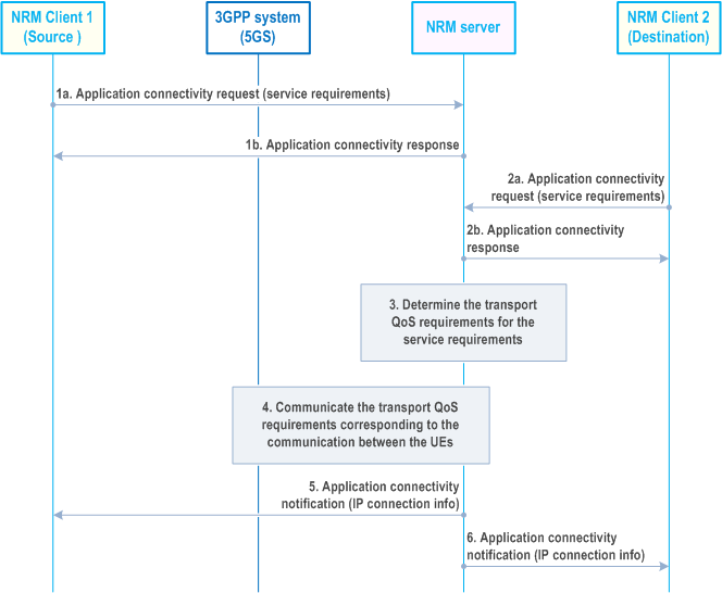
The procedure for establishing Uu-based application-level direct communications between two UEs, with application service requirements is as illustrated in Figure 14.3.9.2.1-1. In this procedure the source and destination VAL clients correlate their triggering of the procedure establishment before the NRM Server provides the service.
Pre-conditions:
- NRM client 1 and NRM client 2 are provided configuration information for the VAL clients served e.g. connectivity requirements, which destination UEs to connect to over Uu, etc.
- The NRM client 1 and NRM client 2 are configured with the information of the NRM server and have connectivity enabled to communicate with the NRM server. The information is provided via pre-configuration.
- The NRM server is configured with policies and information of the UEs to determine authorization of the UEs requesting connectivity via Uu.
- The VAL clients associated with NRM client 1 and NRM client 2 have triggered the establishment of connectivity.

Step 1a.
The NRM client 1 sends the application connectivity request (source identity and IP address, destination identities, service requirements) to the NRM Server. The service requirement from the source includes packet size, packet transmission interval, packet E2E latency, allowed packet loss rate/packet loss amount/packet error rate, etc. The destination may be multiple UEs (devices). The identity of source and destination may be the application user identity or the MAC address.
Step 1b.
The NRM server determines whether the UE of NRM client 1 is authorized to connect to the destination UEs for direct service communications via Uu. If UE of NRM client 1 is authorized to connect to the destination UEs, then a response is provided to the NRM client 1 indicating acceptance of the request.
Step 2a.
The NRM client 2 sends the application connectivity request (destination identity and IP address, source identity, service requirements) to the NRM server. The service requirements from the destination includes the service requirements as described in step 1a.
Step 2b.
The NRM server determines whether the UE of NRM client 2 is authorized to connect to the destination UEs for direct service communications via Uu. If UE of NRM client 2 is authorized to connect to the destination UEs, then a response is provided to the NRM client 2 indicating acceptance of the request.
Step 3.
Based on the service requirements received in step 1 and step 2, the NRM server determines the parameters and patterns for direct service connectivity between the source UE and the destination UE via Uu and also the transport requirements (i.e., QoS requirements for the 3GPP system (e.g. 5GS)). Further, the NRM server derives the individual QoS requirements for the source UE and the destination UE from the transport requirement accordingly, i.e., the QoS requirements required between the source UE of NRM client 1 and the 3GPP network and the QoS requirements required between the destination UE of NRM client 2 and the 3GPP network. This step may also include retrieving the direct link status of the UEs (e.g. PDU Session Status, UE reachability). If the NRM server determines that direct service connectivity via Uu is not authorized or not possible with the given connectivity requirements, it skips step 4 and proceeds to steps 5 and 6, informing each NRM client accordingly.
NRM server will process E2E connectivity establishment between NRM client 1 and NRM client 2 only after it receives the request from NRM client 2. There can be several NRM clients (destinations) which will perform step 2 and NRM server will process their E2E connectivity with NRM client 1 (source) as and when the requests are received by the NRM server.
Step 4.
The NRM server triggers 3GPP system to establish QoS flow between the UE of NRM client 1 and the 3GPP network and the QoS flow between the UE of NRM client 2 and the network with individual QoS requirements derived from step 3 followed the procedure as specified in TS 23.502, TS 23.501.
Step 5.
The NRM server sends the application connectivity notification (connectivity/session information) to NRM client 1 indicating successful establishment of the connectivity. The connectivity/session information may contain the accepted destination identities.
Step 6.
The NRM server sends the application connectivity notification (connectivity/session information) to NRM client 2 indicating successful establishment of the connectivity.
14.3.9.2.2 Procedure triggered by source request and coordinated with destination p. 272
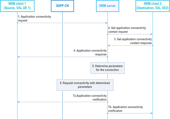
This procedure is used for establishing Uu-based application-level direct communications between two UEs, based on a single client initiating and providing application requirements. The procedure is as illustrated in Figure 14.3.9.2.2-1. The NRM Server provides the service by coordinating with the destination client.
Pre-conditions:
- NRM client 1 and NRM client 2 are provided configuration information for the VAL clients served e.g. connectivity requirements, etc.
- Pre-processing determines that network assisted UE-to-UE communications is required. VAL application policies and destination information for NRM clients are available at the NRM server.
- The VAL client associated with NRM client 1 triggers the establishment of connectivity and provides information about (one or more) destination VAL client(s).

Step 1.
Each NRM client notifies the corresponding VAL client of the established application-level direct UE-to-UE connection.
The NRM client 1 sends the application connectivity request (source identity and IP address, destination identities, application requirements) to the NRM server to establish connectivity for VAL client 1 on UE 1. The destination VAL client(s) may be hosted on one or multiple UEs (devices).
Step 2.
The NRM server determines whether VAL client 1 is authorized to connect to VAL client 2 for application-level direct UE-to-UE communications. If VAL client 1 is authorized to connect to VAL client 2, the NRM server performs the get application connectivity context request to retrieve VAL UE-to-UE connection coordination context procedure as described in clause 14.3.2.56. This step can be skipped if the NRM server is already aware of VAL client 2's context information.
Step 3.
The NRM client 2 sends the get application connectivity context response to the NRM server 2. Using the request information and local policies, the NRM client 2 determines whether context information is to be provided for establishing application-level direct connectivity to the counterpart UE for the VAL application indicated. If the NRM client determines that context information is to be provided, it responds to the NRM server and provides the VAL connection coordination context data for the VAL client served.
Step 4.
The NRM server sends the application connectivity response to NRM client 1.
Step 5.
The NRM server uses VAL client 1's and VAL client 2's context information, their application-level direct UE-to-UE connectivity requirements, location information, and network context as input, checks connectivity service policies, and determines the parameters and patterns for application-level direct UE-to-UE connectivity between the VAL clients. The NRM server may also determine transport requirements (e.g. QoS requirements, for the 3GPP system (e.g. 5GS)). Further, the NRM server derives the individual QoS requirements for the source UE and the destination UE from the transport requirement accordingly, i.e., the QoS requirements required between the source UE of NRM client 1 and the 3GPP network and the QoS requirements required between the destination UE of NRM client 2 and the 3GPP network.
If network provided location information is used, location information may be obtained from the SEAL location management server. Alternatively, Location Reporting monitoring as described in TS 23.502 may be used. This step may also include a request for direct link status (e.g. PDU Session Status, UE reachability, etc. as described in TS 23.502). This action may be skipped if the clients provide location information or if there are no location requirements for establishing the application-level direct UE-to-UE connectivity.
If the NRM server determines that UE-to-UE application-level direct connectivity is not authorized or not possible with the given connectivity requirements, it skips step 5 and proceeds to steps 6 and 7, informing each NRM client accordingly.
Step 6.
The NRM server may request the 3GPP system to establish or modify the QoS flow between the source UE and the network, and the QoS flow between the destination UE and the network that enables the application-level direct UE-to-UE connection for VAL client 1 and VAL client 2 services, e.g. via modification of existing radio bearers. NRM server provides the necessary information (e.g. identifiers of VAL client 1 and VAL client 2, transport requirements) in this request message as per the procedure as specified in TS 23.502, TS 23.501.
Step 7.
a. The NRM server notifies NRM client 1 of the established UE-to-UE connection b. The NRM server notifies the NRM client 2 of the established UE-to-UE connection.
14.3.10 AF influence URSP procedure for reliable transmission |R18| p. 274
14.3.10.1 General p. 274
The procedures related to the AF influence URSP for reliable transmission are described in the following subclauses.
14.3.10.2 AF influence URSP procedure for reliable transmission p. 274
Pre-conditions:
- The SEALDD server (or VAL server) has decided to use reliable transmission for a specific SEALDD client (or VAL client) and has got the UE address or UE ID.

Step 1.
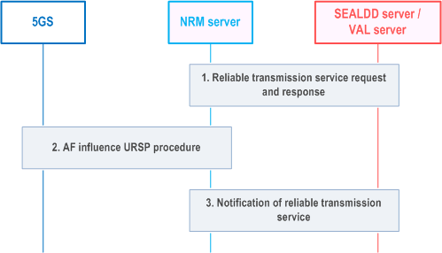
The NRM server receives from the SEALDD server (or VAL server) about the request for reliable transmission service with the application descriptors for the two redundant transmission paths. The SEALDD client's current UE address or UE ID is also provided to identify the affected UE.
Step 2.
After receiving the request from SEALDD server (or VAL server), the NRM server associates the available DNN and S-NSSAI information for the two application descriptors. NRM server triggers via N5/N33 with the AF guidance for URSP procedure as described in clause 4.15.6.10 of TS 23.502. The AF request includes the application traffic descriptors and the associated DNN, S-NSSAI, and also includes UE address or UE ID received in step 1.
Step 3.
NRM server sends response about reliable transmission service.
14.3.11 VAL services over 5GS supporting EPS interworking |R18| p. 275
The VAL server consumes the network resource management services from the NRM server. As specified in TS 23.501, a dedicated user plane anchor point, i.e. UPF + PGW-U function, is defined for interworking between 5GS and EPS. This enables that the network can directly handle PDU sessions (in 5GS) and PDN connections (in EPS) associated to VAL service sessions of a VAL UE during inter-system mobility.
The inter-system mobility of a VAL UE will be transparent to the NRM server and VAL server. The NRM server will continue interacting with the same control plane functions, e.g. PCF, and the VAL server will continue interacting with the same user plane function, e.g. UPF + PGW-U.