Content for TS 23.501 Word version: 19.2.1
1…
3…
4.2.3
4.2.4
4.2.5…
4.2.8…
4.2.8.2.2
4.2.8.2.3…
4.2.8.4…
4.2.9…
4.2.15…
4.3…
4.3.3
4.3.4
4.3.5
4.4…
4.4.6…
4.4.8…
5…
5.3…
5.3.3…
5.4…
5.5…
5.6…
5.6.7…
5.7…
5.7.2…
5.7.3…
5.7.4
5.7.5…
5.8…
5.8.2.11…
5.9…
5.10…
5.11…
5.15…
5.15.11…
5.16…
5.17…
5.18…
5.19…
5.21…
5.22…
5.27…
5.28…
5.29…
5.30…
5.31…
5.32…
5.32.6…
5.33…
5.34…
5.35…
5.38…
5.43…
5.49…
6…
6.3…
6.3.8…
7…
7.2…
8…
8.2.4
8.2.5…
8.3…
A…
D…
E…
F
G…
G.3
G.4…
H…
J
K…
M…
N…
O…
P…
S…
T…
T Network Energy consumption information calculation
T.1 General
T.2 Calculation of Energy Consumption parameters
U Support of traffic offloading at the H-UPF deployed nearby VPLMN for HR PDU Session
U.1 General
U.2 PDU Session establishment for supporting traffic offloading at the H-UPF
U.3 Re-establishment of PDU Session due to UP Path failure
V NR Femto
V.0 General
V.1 NR Femto Deployment Options
W UDP-Option carrying media related information over UDP tunnel
$ Change history
T Network Energy consumption information calculation |R19| p. 723
T.1 General p. 723
This Annex provides examples on how EIF calculate the energy consumption for required granularities.
T.2 Calculation of Energy Consumption parameters p. 723
The energy consumed at a UPF (EUPF )or a gNB (EgNB ) is known over a time window T. And the EIF is aware of the data volume (DV ) consumed at a UPF by a UE (DVUE,UPF ), UE PDU session (DVSession,UPF ) and UE QoS flow (DVFlow,UPF ) over the time interval T. The EIF is aware of the overall data volume at a gNB (DVgNB ), as well as at a UPF (DVUPF ) which serving the UE. Then based on the below example formulas, the required granularities Energy consumption information can be obtained.
To derive the of energy consumed at a gNB over a period of time T by a UE, PDU session, QoS flow, the formulas are:


 To derive the energy consumed at a UPF over a time period T by a UE, session, QoS flow the formulas are:


 To derive the energy consumed in the network in the time interval T by a UE (EUE ), Session (ESession ), QoS flow (EFlow ), the formula is:


EUE,gNB = ∑gNBi∈gNBTUE EUE,gNBi + ∑UPFi ∈ UPFTUE EUE.UPFi
where gNBTUE are all gNBs used by the UE in an interval T, UPFTUE are all UPFs used by the UE in an interval T.
ESession = ∑gNBi∈gNBTSession ESession,gNBi + ∑UPFi ∈ UPFTSession ESession.UPFi
where gNBTSession are all gNBs used by the PDU Session in an interval T, UPFTSession are all UPFs used by the PDU Session in an interval T.
EFlow = ∑gNBi∈gNBTFlow EFlow,gNBi + ∑UPFi ∈ UPFTFlow EFlow.UPFi
where gNBTFlow are all gNBs used by the QoS Flow in an interval T, UPFTFlow are all UPFs used by the QoS Flow in an interval T.
U Support of traffic offloading at the H-UPF deployed nearby VPLMN for HR PDU Session |R19| p. 724
U.1 General p. 724
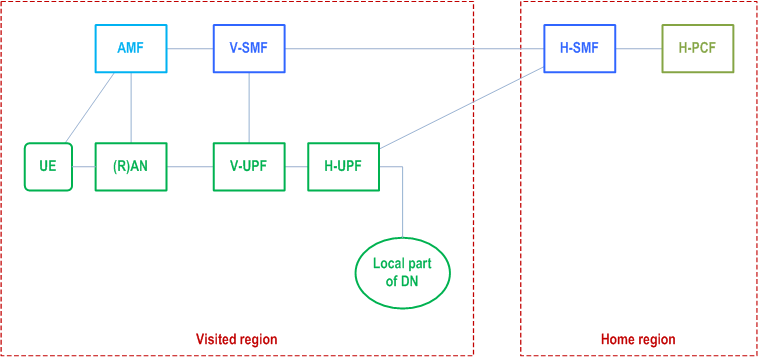
The Home PLMN operator can deploy H-UPFs on sites located physically close to the VPLMN (e.g. visited region) for the support of the local traffic routing at the H-UPF, i.e. home session breakout performed at the H-UPF controlled by H-SMF.

Figure U.1-1 depicts the deployment scenario of H-UPF nearby VPLMN for HR PDU Session for traffic offloading at the H-UPF. For simplicity, other network functions are not shown.
U.2 PDU Session establishment for supporting traffic offloading at the H-UPF p. 724
This clause describes the HR PDU Session establishment for the roaming traffic offloading at the H-UPF deployed nearby VPLMN.
The following are some considerations:
- The H-SMF decides to support roaming traffic offloading at the H-UPF for HR PDU Session based on the configured operator policy
- When performing H-UPF selection as described in clause 6.3.3.3, UE location information (e.g. MNC and MCC of the VPLMN) can be considered in order to select a H-UPF nearby VPLMN for a given HR PDU Session, based on the HPLMN operator policy.
- Based on the operator policy, the selected H-UPF deployed nearby VPLMN can provide the H-SMF with the DNS server information, if it is locally configured, as described in clause 5.8.2.2.
U.3 Re-establishment of PDU Session due to UP Path failure p. 725
For the deployment scenario where the H-UPF of HR PDU Session is deployed nearby VPLMN, if the H-SMF receives from H-UPF the UP Path failure report for the path between the H-UPF (PSA) and V-UPF, the H-SMF acts as described in TS 23.527. If the H-SMF decides to delete the PDU session contexts associated with the path in failure as described in TS 23.527, the H-SMF can trigger release of the HR PDU Session and include an existing cause value indicating that a PDU Session re-establishment is requested. During the new HR PDU Session re-establishment, a new H-UPF is selected based on operator policy.
V NR Femto |R19| p. 726
V.0 General p. 726
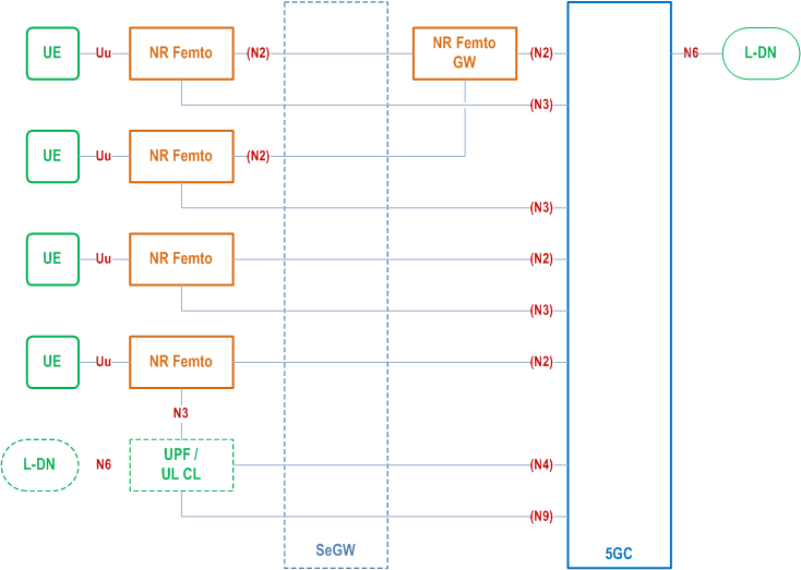
This Annex provides information on how the NF Femto can be deployed and used by means of functionalities defined in clause 5.50 and existing functionalities.
V.1 NR Femto Deployment Options p. 726
Figure V.1-1 depicts the deployment options of NR Femto with a locally deployed UPF close to the location of NR Femto node(s). The locally deployed UPF is a 5GC entity, has a direct N4/N9 interface with the 5GC and can be selected based on the edge computing functionality specified in clause 5.13. The NR Femto GW is optionally used as a concentrator for N2 interface. N3 interface directly goes to a centrally deployed UPF (behind the NR Femto GW) or to a locally deployed UPF (close to NR Femto node location). N3 interface may also go via the NR Femto GW where in this case, the NR Femto GW only performs routing at IP layer.

W (Normative) UDP-Option carrying media related information over UDP tunnel |R19| p. 727
When the DL traffic is end-to end encrypted and transported from the AS proxy through a UDP tunnel established using connect-udp between the AS proxy and the PSA UPF as described in clause 5.37.9.2, the AS proxy generates a XRM packet which inner UDP datagram contains the DL UDP media packets, i.e. QUIC packet between AS proxy and UE and the outer UDP datagram between AS proxy and UPF contains UDP-Option carrying encrypted media related information. Figure W-1 shows XRM packet structure.

After the UPF establishes a QUIC connection to the AS proxy using connect-udp according to clause 5.37.9.2, the AS proxy and the PSA UPF negotiates security keys using connect-udp upgrade token in tunnelled mode. Then the AS proxy encodes media related information into the UDP-Option in outer UDP datagram and uses security keys for encrypting media related information carried in the UDP-Option.