Content for TS 23.501 Word version: 19.2.1
1…
3…
4.2.3
4.2.4
4.2.5…
4.2.8…
4.2.8.2.2
4.2.8.2.3…
4.2.8.4…
4.2.9…
4.2.15…
4.3…
4.3.3
4.3.4
4.3.5
4.4…
4.4.6…
4.4.8…
5…
5.3…
5.3.3…
5.4…
5.5…
5.6…
5.6.7…
5.7…
5.7.2…
5.7.3…
5.7.4
5.7.5…
5.8…
5.8.2.11…
5.9…
5.10…
5.11…
5.15…
5.15.11…
5.16…
5.17…
5.18…
5.19…
5.21…
5.22…
5.27…
5.28…
5.29…
5.30…
5.31…
5.32…
5.32.6…
5.33…
5.34…
5.35…
5.38…
5.43…
5.49…
6…
6.3…
6.3.8…
7…
7.2…
8…
8.2.4
8.2.5…
8.3…
A…
D…
E…
F
G…
G.3
G.4…
H…
J
K…
M…
N…
O…
P…
S…
T…
G SCP Deployment Examples
G.1 General
G.2 An SCP based on service mesh
G.2.1 Introduction
G.2.2 Communication across service mesh boundaries
...
...
G SCP Deployment Examples |R16| p. 664
G.1 General p. 664
This Annex provides deployment examples for the SCP but is not meant to be an exhaustive list of deployment options for the SCP. The first example G.1 is based on an SCP implement using (network wide) service mesh technology, while the second example builds on SCP and 5GC functions as independent deployment units.
G.2 An SCP based on service mesh p. 664
G.2.1 Introduction p. 664
This clause describes an SCP deployment based on a distributed model in which SCP endpoints are co-located with 5GC functionality (e.g. an NF, an NF Service, a subset thereof such as a microservice implementing part of an NF/NF service or a superset thereof such as a group of NFs, NF Services or microservices). This example makes no assumptions as to the internal composition of each 5GC functionality (e.g. whether they are internally composed of multiple elements or whether such internal elements communicate with means other than the service mesh depicted in this example).
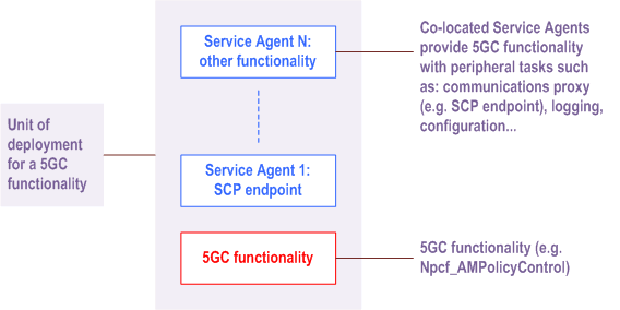
In this deployment example, Service Agent(s) implementing necessary peripheral tasks (e.g. an SCP endpoint) are co-located with 5GC functionality, as depicted in Figure G.2.1-1. In this example, Service Agents and 5GC functionality, although co-located, are separate components.

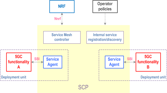
In this deployment example, an SCP Service Agent, i.e. a service communication proxy, is co-located in the same deployment unit with 5GC functionality and provides each deployed unit (e.g. a container-based VNFC) with indirect communication and delegated discovery.
Figure G.2.1-2 shows an overview of this deployment scenario. For SBI-based interactions with other 5GC functionalities, a consumer (5GC functionality A) communicates through its Service Agent via SBI. Its Service Agent selects a target producer based on the request and routes the request to the producer's (5GC functionality B) Service Agent. What routing and selection policies a Service Agent applies for a given request is determined by routing and selection policies pushed by the service mesh controller. Information required by the service mesh controller is pushed by the Service Agents to the service mesh controller.
In this deployment, the SCP manages registration and discovery for communication within the service mesh and it interacts with an external NRF for service exposure and communication across service mesh boundaries. Operator-defined policies are additionally employed to generate the routing and selection policies to be used by the Service Agents.
This example depicts only SBI-based communication via a service mesh, but it does not preclude the simultaneous use of the service mesh for protocols other than SBI supported by the service mesh or that the depicted 5GC functionality additionally communicates via other means.

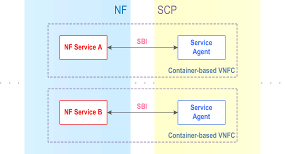
From a 3GPP perspective, in this deployment example a deployment unit thus contains NF functionality and SCP functionality. Figure G.2.1-3 depicts the boundary between both 3GPP entities. In the depicted example, two NF Services part of the same NF and each exposing an SBI interface are deployed each in a container-based VNFC. A co-located Service Agent provides each NF Service with indirect communication and delegated discovery.

G.2.2 Communication across service mesh boundaries p. 665
It is a deployment where a single service mesh covers all functionality within a given deployment or not. In cases of communication across the boundaries of a service mesh, the service mesh routing the outbound message knows neither whether the selected producer is in a service mesh nor the internal topology of the potential service mesh where the producer resides.
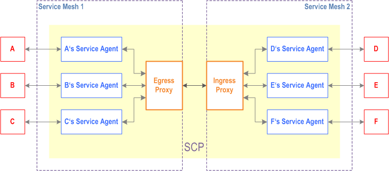
In such a deployment, as shown in Figure G.2.2-1, after producer selection is performed, routing policies on the outgoing service mesh are only aware of the next hop.
Given a request sent by A, A's Service Agent will perform producer selection based on the received request. If the selected producer endpoint (e.g. D) is determined to be outside of Service Mesh 1, A's Service Agent routes the request to the Egress Proxy. For a successful routing, the Egress Proxy needs to be able to determine the next hop of the request. In this case, this is the Ingress Proxy of Service Mesh 2. The Ingress Proxy of Service Mesh 2 is, based on the information in the received request and its routing policies, able to determine the route for the request. Subsequently, D receives the request. No topology information needs to be exchanged between Service Mesh 1 and Service Mesh 2 besides a general routing rule towards Service Mesh 2 (e.g. a FQDN prefix) and an Ingress Proxy destination for requests targeting endpoints in Service Mesh 2.
