Content for TS 23.501 Word version: 19.2.1
1…
3…
4.2.3
4.2.4
4.2.5…
4.2.8…
4.2.8.2.2
4.2.8.2.3…
4.2.8.4…
4.2.9…
4.2.15…
4.3…
4.3.3
4.3.4
4.3.5
4.4…
4.4.6…
4.4.8…
5…
5.3…
5.3.3…
5.4…
5.5…
5.6…
5.6.7…
5.7…
5.7.2…
5.7.3…
5.7.4
5.7.5…
5.8…
5.8.2.11…
5.9…
5.10…
5.11…
5.15…
5.15.11…
5.16…
5.17…
5.18…
5.19…
5.21…
5.22…
5.27…
5.28…
5.29…
5.30…
5.31…
5.32…
5.32.6…
5.33…
5.34…
5.35…
5.38…
5.43…
5.49…
6…
6.3…
6.3.8…
7…
7.2…
8…
8.2.4
8.2.5…
8.3…
A…
D…
E…
F
G…
G.3
G.4…
H…
J
K…
M…
N…
O…
P…
S…
T…
4.2.3 Non-roaming reference architecture p. 45
Figure 4.2.3-1 depicts the non-roaming reference architecture. Service-based interfaces are used within the Control Plane.
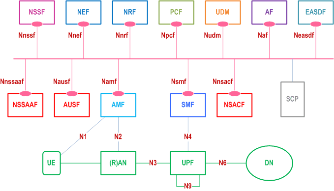
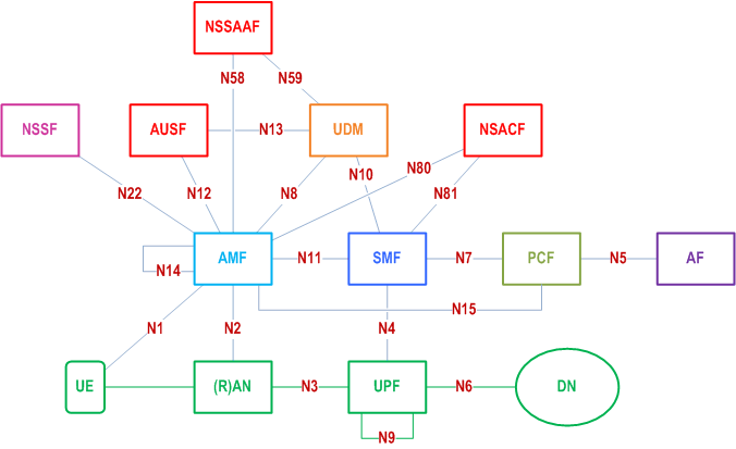
Figure 4.2.3-2 depicts the 5G System architecture in the non-roaming case, using the reference point representation showing how various network functions interact with each other.
Subscription-based routing to a particular core network as specified in clause 6.44 of TS 22.261 enables forwarding of the signalling and user traffic of certain UEs to a target (partner) PLMN that is not the HPLMN of the UE. This is achieved by selecting NFs residing in the target PLMN. The NRF of the HPLMN, with optional support of the NRF in that target PLMN as specified in clause 4.17.4 of TS 23.502, is responsible to provide proper network function instance information during network function discovery and selection.
Figure 4.2.3-3 depicts the non-roaming architecture for UEs concurrently accessing two (e.g. local and central) data networks using multiple PDU Sessions, using the reference point representation. This Figure shows the architecture for multiple PDU Sessions where two SMFs are selected for the two different PDU Sessions. However, each SMF may also have the capability to control both a local and a central UPF within a PDU Session.
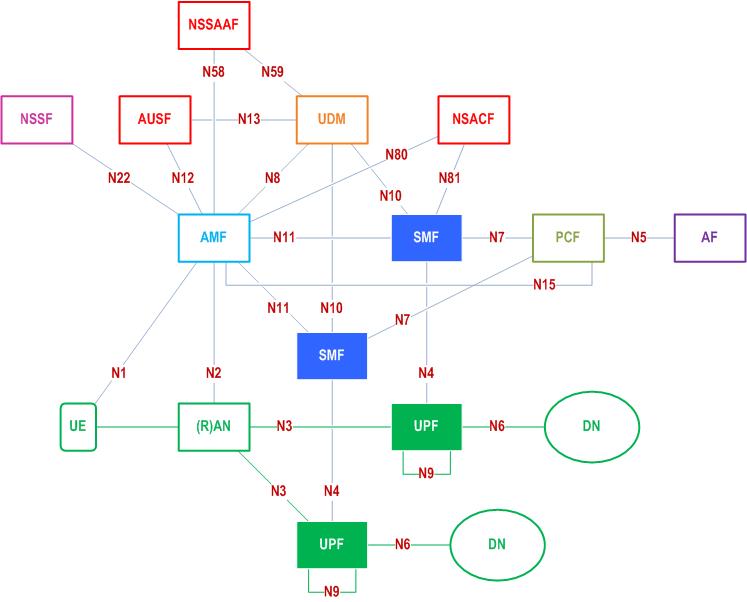
Figure 4.2.3-4 depicts the non-roaming architecture in the case of concurrent access to two (e.g. local and central) data networks is provided within a single PDU Session, using the reference point representation.
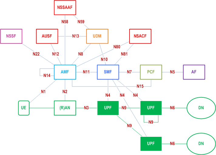
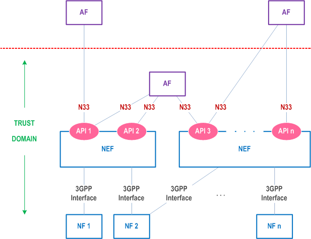
Figure 4.2.3-5 depicts the non-roaming architecture for Network Exposure Function, using reference point representation.
