Content for TS 23.501 Word version: 19.2.1
1…
3…
4.2.3
4.2.4
4.2.5…
4.2.8…
4.2.8.2.2
4.2.8.2.3…
4.2.8.4…
4.2.9…
4.2.15…
4.3…
4.3.3
4.3.4
4.3.5
4.4…
4.4.6…
4.4.8…
5…
5.3…
5.3.3…
5.4…
5.5…
5.6…
5.6.7…
5.7…
5.7.2…
5.7.3…
5.7.4
5.7.5…
5.8…
5.8.2.11…
5.9…
5.10…
5.11…
5.15…
5.15.11…
5.16…
5.17…
5.18…
5.19…
5.21…
5.22…
5.27…
5.28…
5.29…
5.30…
5.31…
5.32…
5.32.6…
5.33…
5.34…
5.35…
5.38…
5.43…
5.49…
6…
6.3…
6.3.8…
7…
7.2…
8…
8.2.4
8.2.5…
8.3…
A…
D…
E…
F
G…
G.3
G.4…
H…
J
K…
M…
N…
O…
P…
S…
T…
4.3.5 Service Exposure in Interworking Scenarios |R16| p. 87
4.3.5.1 Non-roaming architecture p. 87
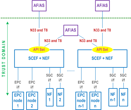
Figure 4.3.5.1-1 shows the non-roaming architecture for Service Exposure for EPC-5GC Interworking. If the UE is capable of mobility between EPS and 5GS, the network is expected to associate the UE with an SCEF+NEF node for Service Capability Exposure.

4.3.5.2 Roaming architectures p. 88
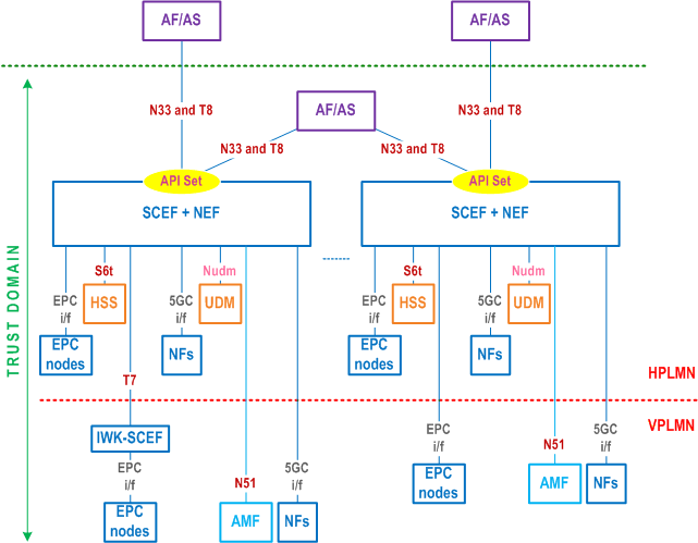
Figure 4.3.5.2-1 represents the roaming architecture for Service Exposure for EPC-5GC Interworking. This architecture is applicable to both the home routed roaming and local breakout roaming.
