Content for TS 23.501 Word version: 19.2.1
1…
3…
4.2.3
4.2.4
4.2.5…
4.2.8…
4.2.8.2.2
4.2.8.2.3…
4.2.8.4…
4.2.9…
4.2.15…
4.3…
4.3.3
4.3.4
4.3.5
4.4…
4.4.6…
4.4.8…
5…
5.3…
5.3.3…
5.4…
5.5…
5.6…
5.6.7…
5.7…
5.7.2…
5.7.3…
5.7.4
5.7.5…
5.8…
5.8.2.11…
5.9…
5.10…
5.11…
5.15…
5.15.11…
5.16…
5.17…
5.18…
5.19…
5.21…
5.22…
5.27…
5.28…
5.29…
5.30…
5.31…
5.32…
5.32.6…
5.33…
5.34…
5.35…
5.38…
5.43…
5.49…
6…
6.3…
6.3.8…
7…
7.2…
8…
8.2.4
8.2.5…
8.3…
A…
D…
E…
F
G…
G.3
G.4…
H…
J
K…
M…
N…
O…
P…
S…
T…
S Architecture examples and protocol stacks for MWAB support
S.1 General
S.2 System architecture for MWAB operation in PLMNs
S.3 Architectures to support MWAB in SNPN case
S.4 Protocol Stacks for MWAB node
S.4.1 Control Plane Protocol Stacks to support N2 interface for MWAB node
S.4.2 User Plane Protocol Stacks to support N3 interface for MWAB node
S Architecture examples and protocol stacks for MWAB support |R19| p. 717
S.1 General p. 717
This Annex provides system architecture examples for MWAB operations in PLMN cases and NPN cases. The example protocol stacks for the MWAB support are also provided.
S.2 System architecture for MWAB operation in PLMNs p. 717
Figure S.2-1 and Figure S.2-2 present an example architecture for the MWAB operation when no roaming was involved for the MWAB-UE. In this case, there may be one or two PLMNs involved, i.e. the BH PLMN that serves the MWAB-UE and the MWAB Broadcasted PLMN that serves the UE connected to the MWAB can be the same or different.
The MWAB-gNB logically belongs to MWAB Broadcasted PLMN and announces the PLMN IDs of the MWAB Broadcasted PLMN. The MWAB-gNB establishes N2 and N3 connection with the UE AMF and UE UPF in the MWAB Broadcasted PLMN via the PDU session of the MWAB-UE established with BH PLMN.
The BH UPF in the BH PLMN serves the MWAB-UE and provides the connection via a N6 interface towards the MWAB Broadcasted PLMN, to carry the N2 and N3 traffic from MWAB-gNB. The BH UPF also supports the access to the OAM servers in the MWAB Broadcasted PLMN by the MWAB-gNB.
UE connected to the MWAB-gNB can access the 5GS services offered by MWAB Broadcasted PLMN. No MWAB specific enhancement to the UE is required. The UE connected to the MWAB-gNB is not aware of the BH PLMN and thus does not need any roaming agreement between its HPLMN and the BH PLMN.
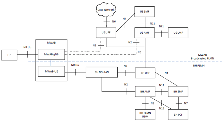
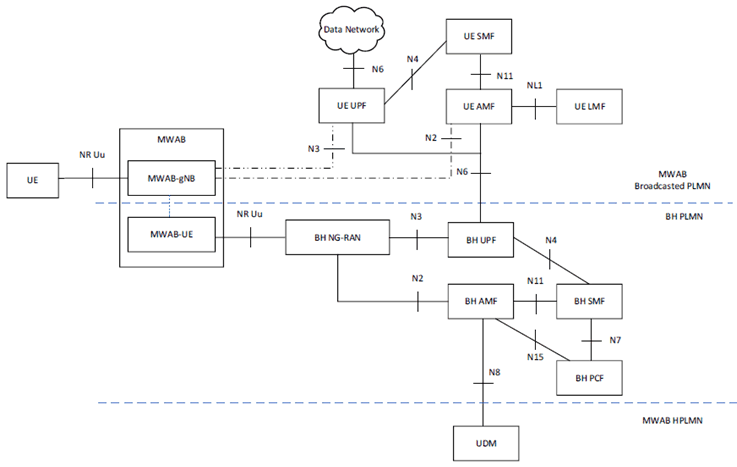
Figure S.2-3 presents an example architecture for the MWAB operation when MWAB-UE is roaming with a Local Breakout PDU Session for its operation. In this case, there may be three PLMNs involved, i.e. the BH PLMN that serves the MWAB-UE and the MWAB Broadcasted PLMN that serves the UE connected to the MWAB and the HPLMN of the MWAB-UE. The use of the Local Breakout PDU Session by the MWAB-UE can be configured by its HPLMN, e.g. with some VPLMN specific URSP rules. In some cases, the BH PLMN and MWAB Broadcasted PLMN can be the same PLMN as illustrated in Figure S.2-1.
The BH PLMN can access the MWAB-UE's HPLMN UDM for the subscription information. The rest of the operations are similar to that shown in Figure S.2-1 and Figure S.2-2.
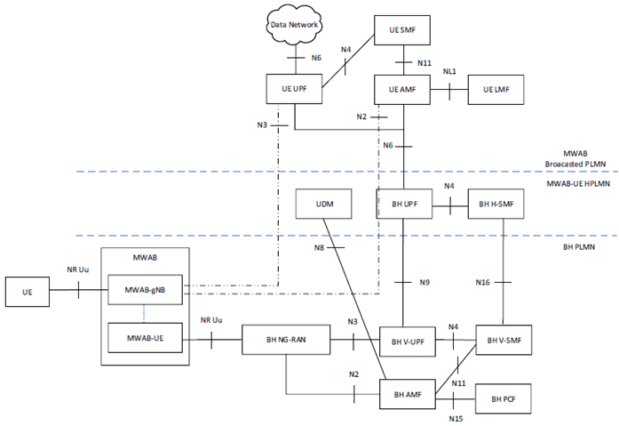
Figure S.2-4 presents an example architecture for the MWAB operation when MWAB-UE is roaming with a Home Routed PDU session for its operation. In this case, PDU session of the MWAB-UE is routed by BH PLMN to the HPLMN of the MWAB-UE. The rest of the operations are similar to that shown in Figure S.2-3. In some cases, the BH PLMN and MWAB Broadcasted PLMN can be the same PLMN as illustrated in Figure S.2-1.
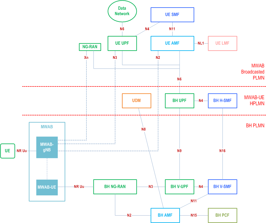
In Figure S.2-1, Figure S.2-2, Figure S.2-3 and Figure S.2-4, if the UE served by the MWAB is roaming, there can be another PLMN (not shown in the Figures), i.e. the HPLMN of the UE served by the MWAB, involved. The interaction of the HPLMN of the UE and the MWAB Broadcasted PLMN follows that described in clause 4.2.4 for the roaming case. The UE served by the MWAB-gNB is not aware of BH PLMN and thus does not need any roaming agreement between its HPLMN and the BH PLMN.
S.3 Architectures to support MWAB in SNPN case p. 719
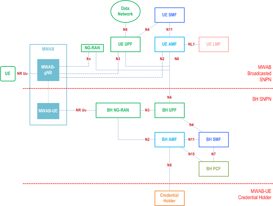
The MWAB operation also supports SNPN, and the corresponding architectures are presented in Figure S.3-1, Figure S.3-2 and Figure S.3-3. The MWAB operation also supports mixed PLMN and SNPN operation, i.e. in the architecture presented in Figure S.3-1, Figure S.3-2 and Figure S.3-3, the BH SNPN can be replaced by a PLMN and MWAB Broadcasted SNPN remains a SNPN. The SNPN operations as described in clause 5.30 apply to the MWAB-UE and the UE served by the MWAB-gNB.
Figure S.3-1 and Figure S.3-2 present example architectures for the MWAB operation when the serving SNPN of the MWAB-UE is the same as subscribed SNPN of MWAB-UE. In this case, there may be two SNPNs involved, i.e. the BH SNPN that serves the MWAB-UE and the MWAB Broadcasted SNPN that serves the UE connected to the MWAB-gNB. The MWAB-gNB establishes N2 and N3 connection with the UE AMF and UE UPF via the PDU session of the MWAB-UE established with BH SNPN. MWAB-gNB announces SNPN ID of MWAB Broadcasted SNPN.
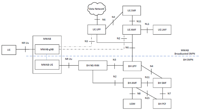
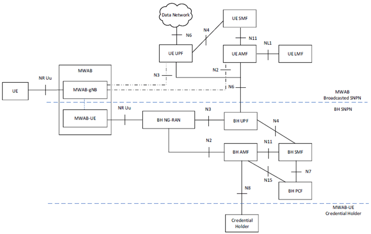
Figure S.3-3 presents an example architecture for the MWAB operation when the MWAB-UE accesses its serving SNPN using credentials owned by a Credential Holder. In this case, besides the two SNPNs, i.e. the BH SNPN that serves the MWAB-UE and the MWAB Broadcasted SNPN that serves the UE connected to the MWAB-gNB, the Credential Holder of MWAB-UE is also involved. The MWAB-gNB establishes N2 and N3 connection with the UE AMF and UE UPF via the PDU session of the MWAB-UE established with BH SNPN. MWAB-gNB announces SNPN ID of the MWAB Broadcasted SNPN.
S.4 Protocol Stacks for MWAB node p. 721
S.4.1 Control Plane Protocol Stacks to support N2 interface for MWAB node p. 721
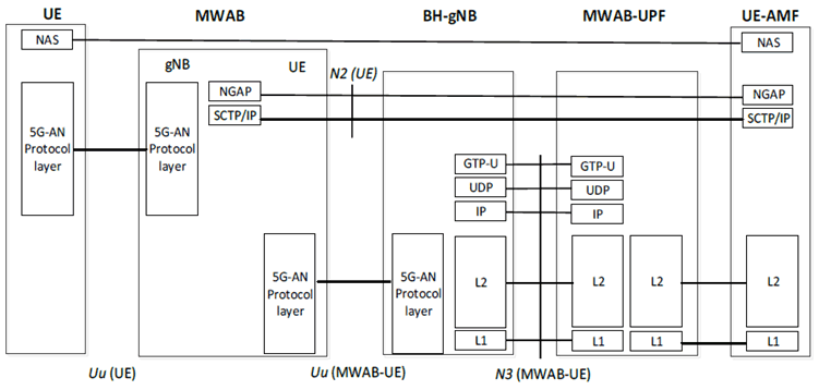
Figure S.4.1-1 illustrates the Control Plane Protocol Stacks to support the N2 interface. A PDU session between MWAB-UE and MWAB-UPF is established as a backhaul link to support the overlayed N2 interface. The N2 interface terminates at MWAB-gNB and UE-AMF respectively, which includes NGAP and SCTP/IP layer protocols between them.
S.4.2 User Plane Protocol Stacks to support N3 interface for MWAB node p. 722
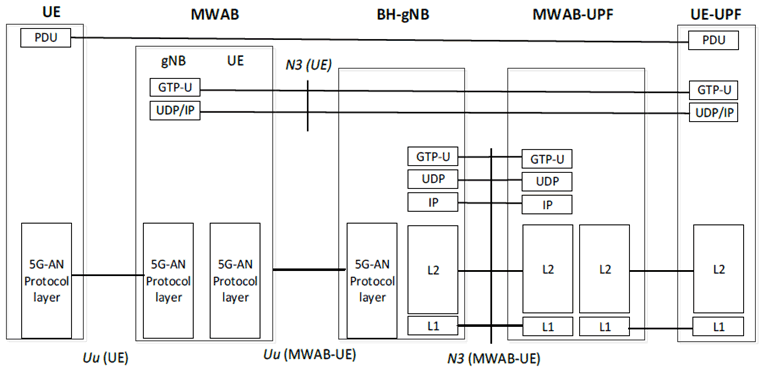
Figure S.4.2-1 illustrates the User Plane Protocol Stacks to support the N3 interface. A PDU session between MWAB-UE and MWAB-UPF is established as a backhaul link to support the overlayed N3 interface. The N3 interface terminates at MWAB-gNB and UE-UPF, which includes GTP-U and UDP/IP layer protocols between them. A PDU session between UE and UE-UPF is realized by:
- the Uu between UE and MWAB-gNB; and
- the N3 between MWAB-gNB and UE-UPF on top of the backhauling PDU session between MWAB-UE and MWAB-UPF.