Content for TS 38.321 Word version: 18.3.0
1…
4…
5…
5.1.2…
5.2…
5.4…
5.4.4…
5.5…
5.9…
5.18…
5.18.18…
5.19…
5.22…
5.22.1.4…
5.22.2…
5.23…
6…
6.1.3…
6.1.3.8…
6.1.3.11…
6.1.3.17…
6.1.3.21…
6.1.3.26…
6.1.3.31…
6.1.3.37…
6.1.3.42…
6.1.3.49…
6.1.3.53…
6.1.3.59…
6.1.3.64…
6.1.3.70…
6.1.3.74…
6.1.3.79…
6.1.4…
6.2…
7…
6.1.3.49 Enhanced Multiple Entry PHR MAC CE
6.1.3.50 Enhanced Single Entry PHR for multiple TRP MAC CE
6.1.3.51 Enhanced Multiple Entry PHR for multiple TRP MAC CE
6.1.3.52 Sidelink DRX Command MAC CE
...
...
6.1.3.49 Enhanced Multiple Entry PHR MAC CE |R17| p. 262
The Enhanced Multiple Entry PHR MAC CE is identified by a MAC subheader with eLCID as specified in Table 6.2.1-2b. It has a variable size with following fields:
- Ci: This field indicates the presence of PH field(s) for the Serving Cell with ServCellIndex i as specified in TS 38.331. The Ci field set to 1 indicates that PH field(s) for the Serving Cell with ServCellIndex i is reported. The Ci field set to 0 indicates that a PH field for the Serving Cell with ServCellIndex i is not reported;
- R: Reserved bit, set to 0;
- V: This field indicates if the PH value is based on a real transmission or a reference format. For Type 1 PH, the V field set to 0 indicates real transmission on PUSCH and the V field set to 1 indicates that a PUSCH reference format is used. For Type 2 PH, the V field set to 0 indicates real transmission on PUCCH and the V field set to 1 indicates that a PUCCH reference format is used. For Type 3 PH, the V field set to 0 indicates real transmission on SRS and the V field set to 1 indicates that an SRS reference format is used. Furthermore, for Type 1, Type 2, and Type 3 PH, the V field set to 0 indicates the presence of the octet containing the associated PCMAX,f,c field and the MPE field, and the V field set to 1 indicates that the octet containing the associated PCMAX,f,c field and the MPE field is omitted;
- Power Headroom (PH): This field indicates the power headroom level. The length of the field is 6 bits. The reported PH and the corresponding power headroom levels are shown in Table 6.1.3.8-1 (the corresponding measured values in dB for the NR Serving Cell are specified in TS 38.133 while the corresponding measured values in dB for the E-UTRA Serving Cell are specified in TS 36.133);
- P: If mpe-Reporting-FR2 is configured and the Serving Cell operates on FR2, the MAC entity shall set this field to 0 if the applied P-MPR value, to meet MPE requirements, as specified in TS 38.101-2, is less than P-MPR_00 as specified in TS 38.133 and to 1 otherwise. If mpe-Reporting-FR2 is not configured or the Serving Cell operates on FR1, this field indicates whether power backoff is applied due to power management (as allowed by P-MPRc as specified in TS 38.101-1, TS 38.101-2, and TS 38.101-3). The MAC entity shall set the P field to 1 if the corresponding PCMAX,f,c field would have had a different value if no power backoff due to power management had been applied;
- PCMAX,f,c: If present, this field indicates the PCMAX,f,c (as specified in TS 38.213) for the NR Serving Cell and the PCMAX,c or P̃CMAX,c (as specified in TS 36.213) for the E-UTRA Serving Cell used for calculation of the preceding PH field. The reported PCMAX,f,c and the corresponding nominal UE transmit power levels are shown in Table 6.1.3.8-2 (the corresponding measured values in dBm for the NR Serving Cell are specified in TS 38.133 while the corresponding measured values in dBm for the E-UTRA Serving Cell are specified in TS 36.133);
- MPE: If mpe-Reporting-FR2 is configured, and the Serving Cell operates on FR2, and if the P field is set to 1, this field indicates the applied power backoff to meet MPE requirements, as specified in TS 38.101-2. This field indicates an index to Table 6.1.3.8-3 and the corresponding measured values of P-MPR levels in dB are specified in TS 38.133. The length of the field is 2 bits. If mpe-Reporting-FR2 is not configured, or if the Serving Cell operates on FR1, or if the P field is set to 0, R bits are present instead;
- Bi: This field indicates whether the candidate beam information identified by either Resourcei is present or not. If the B1 field is set to 1, the first octet containing Resource1 is present and if the B2 field is set to 1, the second octet containing Resource2 is present, and so on.
- Pi: If mpe-Reporting-FR2-r17 is configured and the Serving Cell operates on FR2, the MAC entity shall set this field to 0 if the applied P-MPR value, to meet MPE requirements, as specified in TS 38.101-2, is less than P-MPR_00 as specified in TS 38.133 and to 1 otherwise;
- MPEi: If mpe-Reporting-FR2-r17 is configured, and the Serving Cell operates on FR2, and if the corresponding P i field is set to 1, this field indicates the applied power backoff to meet MPE requirements, as specified in TS 38.101-2. This field indicates an index to Table 6.1.3.8-3 and the corresponding measured values of P-MPR levels in dB are specified in TS 38.133. The length of the field is 2 bits. If mpe-Reporting-FR2-r17 is not configured, or if the Serving Cell operates on FR1, or if the P i field is set to 0, R bits are present instead;
- Resourcei: This field indicates the candidate beam identified by by the number of entries in the corresponding mpe-ResourcePoolToAddModList as specified in TS 38.331. The length of this field 6 bits.
- R: Reserved bit, set to 0.


6.1.3.50 Enhanced Single Entry PHR for multiple TRP MAC CE |R17| p. 267
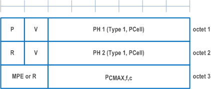
The Enhanced Single Entry PHR for multiple TRP MAC CE is identified by a MAC subheader with eLCID as specified in Table 6.2.1-2b.
The two PHs together with one PCMAX,f,c for the Serving Cell are reported if UE is configured with twoPHRMode with the multiple TRP PUSCH repetition feature is configured.
It has a fixed size and consists of three octets defined as follows (Figure 6.1.3.50-1):
- R: Reserved bit, set to 0;
- Power Headroom i (PH i): This field indicates the power headroom level, where PH 1 is associated with the SRS-ResourceSet with a lower srs-ResourceSetId and PH 2 is associated with the SRS-ResourceSet with a higher srs-ResourceSetId. PH fields for a Serving Cell are included in ascending order based on i. The length of the field is 6 bits. The reported PH and the corresponding power headroom levels are shown in Table 6.1.3.8-1 (the corresponding measured values in dB are specified in TS 38.133);
- P: If mpe-Reporting-FR2 is configured and the Serving Cell operates on FR2, the MAC entity shall set this field to 0 if the applied P-MPR value, to meet MPE requirements, as specified in TS 38.101-2, is less than P-MPR_00 as specified in TS 38.133 and to 1 otherwise. If mpe-Reporting-FR2 is not configured or the Serving Cell operates on FR1, this field indicates whether power backoff is applied due to power management (as allowed by P-MPRc as specified in TS 38.101-1, TS 38.101-2, and TS 38.101-3). The MAC entity shall set the P field to 1 if the corresponding PCMAX,f,c field would have had a different value if no power backoff due to power management had been applied;
- V: This field indicates if the PH value for the corresponding TRP is based on a real transmission or a reference format. For Type 1 PH, the V field set to 0 indicates real transmission on PUSCH and the V field set to 1 indicates that a PUSCH reference format is used;
- PCMAX,f,c: This field indicates the PCMAX,f,c (as specified in TS 38.213) used for calculation of the preceding PH fields. The reported PCMAX,f,c and the corresponding nominal UE transmit power levels are shown in Table 6.1.3.8-2 (the corresponding measured values in dBm are specified in TS 38.133);
- MPE: If mpe-Reporting-FR2 is configured, and the Serving Cell operates on FR2, and if the P field is set to 1, this field indicates the applied power backoff to meet MPE requirements, as specified in TS 38.101-2. This field indicates an index to Table 6.1.3.8-3 and the corresponding measured values of P-MPR levels in dB are specified in TS 38.133. The length of the field is 2 bits. If mpe-Reporting-FR2 is not configured, or if the Serving Cell operates on FR1, or if the P field is set to 0, R bits are present instead.

6.1.3.51 Enhanced Multiple Entry PHR for multiple TRP MAC CE |R17| p. 267
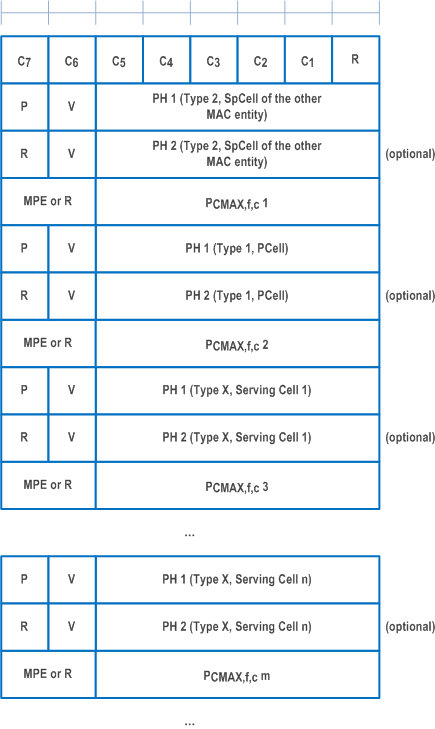
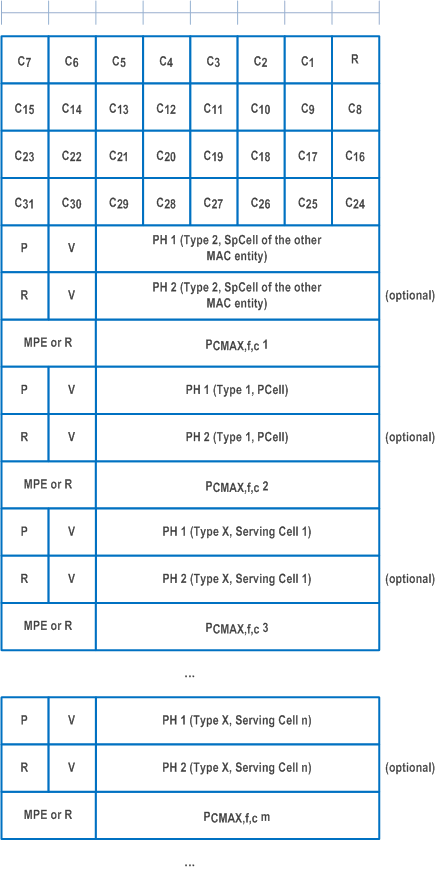
The Enhanced Multiple Entry PHR for multiple TRP MAC CE is identified by a MAC subheader with eLCID as specified in Table 6.2.1-2b.
It has a variable size, and includes the bitmaps, a Type 2 PH field and an octet containing the associated PCMAX,f,c field (if reported) for SpCell of the other MAC entity, a Type 1 PH field and an octet containing the associated PCMAX,f,c field (if reported) for the PCell. It further includes, in ascending order based on the ServCellIndex, one or multiple of Type X PH fields and octets containing the associated PCMAX,f,c fields (if reported) for Serving Cells other than PCell indicated in the bitmap for indicating the presence of PH(s). X is either 1 or 3 according to TS 38.213 and TS 36.213.
The presence of Type 2 PH field for SpCell of the other MAC entity is configured by phr-Type2OtherCell with value true.
A single octet bitmap is used for indicating the presence of PH(s) per Serving Cell when the highest ServCellIndex of Serving Cell with configured uplink is less than 8, otherwise four octets are used.
The MAC entity determines whether PH value for an activated Serving Cell is based on real transmission or a reference format by considering the configured grant(s) and downlink control information which has been received until and including the PDCCH occasion in which the first UL grant for a new transmission that can accommodate the MAC CE for PHR as a result of LCP as defined in clause 5.4.3.1 is received since a PHR has been triggered if the PHR MAC CE is reported on an uplink grant received on the PDCCH or until the first uplink symbol of PUSCH transmission minus PUSCH preparation time as defined in clause 7.7 of TS 38.213 if the PHR MAC CE is reported on a configured grant.
For a band combination in which the UE does not support dynamic power sharing, the UE may omit the octets containing Power Headroom field and PCMAX,f,c field for Serving Cells in the other MAC entity except for the PCell in the other MAC entity and the reported values of Power Headroom and PCMAX,f,c for the PCell are up to UE implementation.
The two PHs together with one PCMAX,f,c for the Serving Cell configured with the multiple TRP PUSCH repetition feature is configured are reported if the MAC entity is configured with twoPHRMode.
The Enhanced Multiple Entry PHR for multiple TRP MAC CEs are defined as follows:
- Ci: This field indicates the presence of PH field(s) for the Serving Cell with ServCellIndex i as specified in TS 38.331. The Ci field set to 1 indicates that PH field(s) for the Serving Cell with ServCellIndex i is reported. The Ci field set to 0 indicates that a PH field for the Serving Cell with ServCellIndex i is not reported;
- R: Reserved bit, set to 0;
- V: This field indicates if the PH value is based on a real transmission or a reference format. For Type 1 PH, the V field set to 0 indicates real transmission on PUSCH and the V field set to 1 indicates that a PUSCH reference format is used. For Type 2 PH, the V field set to 0 indicates real transmission on PUCCH and the V field set to 1 indicates that a PUCCH reference format is used. For Type 3 PH, the V field set to 0 indicates real transmission on SRS and the V field set to 1 indicates that an SRS reference format is used. Furthermore, for Type 1, Type 2, and Type 3 PH, the V field set to 0 indicates the presence of the octet containing the associated PCMAX,f,c field and the MPE field, and all of the V field(s) for the Serving Cell set to 1 indicates that the octet containing the associated PCMAX,f,c field and the MPE field is omitted;
- Power Headroom i (PH i): This field indicates the power headroom level, where PH 1 is associated with the SRS-ResourceSet with a lower srs-ResourceSetId and PH 2 is associated with the SRS-ResourceSet with a higher srs-ResourceSetId. PH fields for a Serving Cell are included in ascending order based on i. The length of the field is 6 bits. The reported PH and the corresponding power headroom levels are shown in Table 6.1.3.8-1 (the corresponding measured values in dB for the NR Serving Cell are specified in TS 38.133 while the corresponding measured values in dB for the E-UTRA Serving Cell are specified in TS 36.133);
- P: If mpe-Reporting-FR2 is configured and the Serving Cell operates on FR2, the MAC entity shall set this field to 0 if the applied P-MPR value, to meet MPE requirements, as specified in TS 38.101-2, is less than P-MPR_00 as specified in TS 38.133 and to 1 otherwise. If mpe-Reporting-FR2 is not configured or the Serving Cell operates on FR1, this field indicates whether power backoff is applied due to power management (as allowed by P-MPRc as specified in TS 38.101-1, TS 38.101-2, and TS 38.101-3). The MAC entity shall set the P field to 1 if the corresponding PCMAX,f,c field would have had a different value if no power backoff due to power management had been applied;
- PCMAX,f,c: If present, this field indicates the PCMAX,f,c (as specified in TS 38.213) for the NR Serving Cell and the PCMAX,c or P̃CMAX,c (as specified in TS 36.213) for the E-UTRA Serving Cell used for calculation of the preceding PH field. The reported PCMAX,f,c and the corresponding nominal UE transmit power levels are shown in Table 6.1.3.8-2 (the corresponding measured values in dBm for the NR Serving Cell are specified in TS 38.133 while the corresponding measured values in dBm for the E-UTRA Serving Cell are specified in TS 36.133);
- MPE: If mpe-Reporting-FR2 is configured, and the Serving Cell operates on FR2, and if the P field is set to 1, this field indicates the applied power backoff to meet MPE requirements, as specified in TS 38.101-2. This field indicates an index to Table 6.1.3.8-3 and the corresponding measured values of P-MPR levels in dB are specified in TS 38.133. The length of the field is 2 bits. If mpe-Reporting-FR2 is not configured, or if the Serving Cell operates on FR1, or if the P field is set to 0, R bits are present instead.


6.1.3.52 Sidelink DRX Command MAC CE |R17| p. 270
The Sidelink DRX Command MAC CE is identified by a MAC subheader with LCID as specified in Table 6.2.4-1. The priority of the Sidelink DRX Command MAC CE is fixed to '1'.
It has a fixed size of zero bits.
SL DRX Command MAC CE is only supported in sidelink unicast.