Content for TS 38.321 Word version: 18.3.0
1…
4…
5…
5.1.2…
5.2…
5.4…
5.4.4…
5.5…
5.9…
5.18…
5.18.18…
5.19…
5.22…
5.22.1.4…
5.22.2…
5.23…
6…
6.1.3…
6.1.3.8…
6.1.3.11…
6.1.3.17…
6.1.3.21…
6.1.3.26…
6.1.3.31…
6.1.3.37…
6.1.3.42…
6.1.3.49…
6.1.3.53…
6.1.3.59…
6.1.3.64…
6.1.3.70…
6.1.3.74…
6.1.3.79…
6.1.4…
6.2…
7…
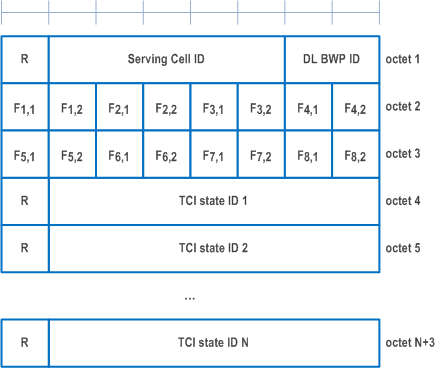
6.1.3.70 Enhanced Unified TCI States Activation/Deactivation MAC CE for Joint TCI States
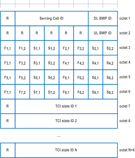
6.1.3.71 Enhanced Unified TCI States Activation/Deactivation MAC CE for Separate TCI States
6.1.3.72 Delay Status Report MAC CE
6.1.3.73 PSI-Based SDU Discard Activation/Deactivation MAC CE
...
...
6.1.3.70 Enhanced Unified TCI States Activation/Deactivation MAC CE for Joint TCI States |R18| p. 291
The Enhanced Unified TCI States Activation/Deactivation MAC CE for Joint TCI States is identified by a MAC subheader with eLCID as specified in Table 6.2.1-1b. It has a variable size consisting of following fields:
- Serving Cell ID: This field indicates the identity of the Serving Cell for which the MAC CE applies. The length of the field is 5 bits. If the indicated Serving Cell is configured as part of a simultaneousU-TCI-UpdateList1, simultaneousU-TCI-UpdateList2, simultaneousU-TCI-UpdateList3 or simultaneousU-TCI-UpdateList4 as specified in TS 38.331, this MAC CE applies to all theServing Cells in the set simultaneousU-TCI-UpdateList1, simultaneousU-TCI-UpdateList2, simultaneousU-TCI-UpdateList3 or simultaneousU-TCI-UpdateList4, respectively;
- DL BWP ID: This field indicates a DL BWP for which the MAC CE applies as the codepoint of the DCI bandwidth part indicator field as specified in TS 38.212. The length of the BWP ID field is 2 bits;
- Fi,j: This field indicates for the TCI state ID fields associated with the codepoint i of the DCI Transmission Configuration Indication field whether the j-th joint TCI state is present or not, where j=1, 2. If Fi,j field is set to 1, it indicates the j-th joint TCI state for codepoint i is present. If Fi,j field is set to 0, it indicates the j-th joint TCI state for codepoint i is absent. The codepoint to which a TCI state is mapped is determined by its ordinal position among all the TCI state ID fields;
- TCI state ID: This field indicates the 7-bits length TCI state ID identified by TCI-StateId as specified in TS 38.331. The maximum number of activated TCI states is 16;
- R: Reserved bit, set to 0.
6.1.3.71 Enhanced Unified TCI States Activation/Deactivation MAC CE for Separate TCI States |R18| p. 292
The Enhanced Unified TCI States Activation/Deactivation MAC CE CE for Separate TCI States is identified by a MAC subheader with eLCID as specified in Table 6.2.1-1b. It has a variable size consisting of following fields:
- Serving Cell ID: This field indicates the identity of the Serving Cell for which the MAC CE applies. The length of the field is 5 bits. If the indicated Serving Cell is configured as part of a simultaneousU-TCI-UpdateList1, simultaneousU-TCI-UpdateList2, simultaneousU-TCI-UpdateList3 or simultaneousU-TCI-UpdateList4 as specified in TS 38.331, this MAC CE applies to all theServing Cells in the set simultaneousU-TCI-UpdateList1, simultaneousU-TCI-UpdateList2, simultaneousU-TCI-UpdateList3 or simultaneousU-TCI-UpdateList4, respectively;
- DL BWP ID: This field indicates a DL BWP for which the MAC CE applies as the codepoint of the DCI bandwidth part indicator field as specified in TS 38.212. The length of the BWP ID field is 2 bits;
- UL BWP ID: This field indicates a UL BWP for which the MAC CE applies as the codepoint of the DCI bandwidth part indicator field as specified in TS 38.212. The length of the BWP ID field is 2 bits;
- Fi,j: This field indicates for the TCI state ID fields associated with the codepoint i of the DCI Transmission Configuration Indication field whether the j-th DL TCI state is present or not, where j=1, 2. If Fi,j field is set to 1, it indicates the j-th DL TCI state for codepoint i is present. If Fi,j field is set to 0, it indicates the j-th DL TCI state for codepoint i is absent;
- Si,j: This field indicates for the TCI state ID fields associated with the codepoint i of the DCI Transmission Configuration Indication field whether the j-th UL TCI state is present or not, where j=1, 2. If Si,j field is set to 1, it indicates the j-th UL TCI state for codepoint i is present. If Si,j field is set to 0, it indicates the j-th UL TCI state for codepoint i is absent;
- TCI state ID: This field indicates the TCI state identified by TCI-StateId as specified in TS 38.331. If the indicated TCI state ID is DL TCI state, 7-bits length TCI state ID, i.e. TCI-StateId, as specified in TS 38.331 is used. If the indicated TCI state ID is UL TCI state, the most significant bit of TCI state ID is considered as the reserved bit and remainder 6 bits indicate the TCI-UL-State-Id as specified in TS 38.331. TCI state IDs are in the order of indication of Fi,j and Si,j fields. The codepoint to which a TCI state is mapped is determined by its ordinal position among all the TCI state ID fields. The maximum number of activated TCI states is 32;
- R: Reserved bit, set to 0.
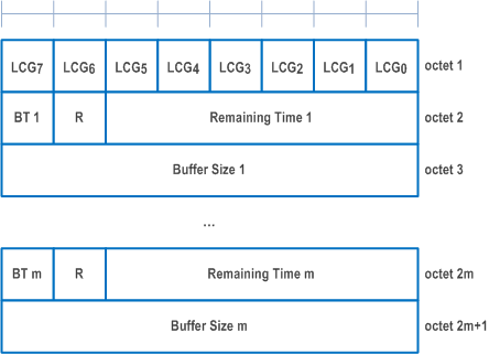
6.1.3.72 Delay Status Report MAC CE |R18| p. 293
The Delay Status Report (DSR) MAC CE is identified by MAC subheader with an eLCID as specified in Table 6.2.1-2b.
The fields in the DSR MAC CE are defined as follows:
- LCGi: This field indicates the presence of delay information (i.e. the Remaining Time and Buffer Size fields) for the LCG i. The LCGi field set to 1 indicates that the delay information for the LCG i is reported. The LCGi field set to 0 indicates that the delay information for the LCG i is not reported;
- Remaining Time: This field indicates the shortest remaining value of running PDCP discardTimer (described in clause 7.3 of TS 38.323) among all PDCP SDUs that are buffered for an LCG but have not been transmitted in any MAC PDU, at the time of the first symbol of the first PUSCH transmission that includes this DSR MAC CE. The length of this field is 6 bits. This field is present only if the buffer size indicated by the corresponding Buffer Size field is not zero; otherwise, this field is reserved and set to 0. If present, the value r in this field indicates a remaining time within the range of (r, r + 1] msec;
- BT: This field is present only if the corresponding LCG is configured with additionalBS-TableAllowed and the buffer size indicated by the corresponding Buffer Size field is not zero; otherwise, this field is reserved and set to 0. If present, the BT field set to 1 indicates that the buffer sizes specified in Table 6.1.3.1-3 are used to set the value of the Buffer Size field, while the BT field set to 0 indicates that the buffer sizes specified in Table 6.1.3.1-2 are used instead;
- Buffer Size: The Buffer Size field indicates the total amount of delay-critical UL data for an LCG according to the data volume calculation procedure specified in clause 5.5 of TS 38.322 and clause 5.15 of TS 38.323 for the associated RLC and PDCP entities, respectively, after the MAC PDU has been built. If the corresponding LCG is configured with additionalBS-TableAllowed and the amount of delay-critical UL data for an LCG is within the buffer sizes specified in Table 6.1.3.1-3, the MAC entity shall use the buffer sizes specified in Table 6.1.3.1-3 to set the value of this field; otherwise, the MAC entity shall use Table 6.1.3.1-2 instead. This field is indicated in number of bytes. The length of this field is 8 bits;
- R: Reserved bit, set to 0.
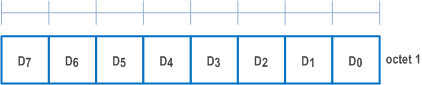
6.1.3.73 PSI-Based SDU Discard Activation/Deactivation MAC CE |R18| p. 294
The PSI-Based SDU Discard Activation/Deactivation MAC CE is identified by MAC subheader with an one-octet eLCID as specified in Table 6.2.1-1b.
It has a fixed size and consists of one octet defined as follows (Figure 6.1.3.73-1):
- Di: This field indicates the activation/deactivation status of the PSI-based SDU discard of DRB i, where i is the ascending order of the DRB ID among the DRBs configured with discardTimerForLowImportance and with RLC entity(ies) associated with this MAC entity. The Di field set to 1 indicates that the PSI-based SDU discard shall be activated for DRB i. The Di field set to 0 indicates that the PSI-based SDU discard shall be deactivated for DRB i.
![]()
![]()
![]()