Content for TS 38.321 Word version: 18.3.0
1…
4…
5…
5.1.2…
5.2…
5.4…
5.4.4…
5.5…
5.9…
5.18…
5.18.18…
5.19…
5.22…
5.22.1.4…
5.22.2…
5.23…
6…
6.1.3…
6.1.3.8…
6.1.3.11…
6.1.3.17…
6.1.3.21…
6.1.3.26…
6.1.3.31…
6.1.3.37…
6.1.3.42…
6.1.3.49…
6.1.3.53…
6.1.3.59…
6.1.3.64…
6.1.3.70…
6.1.3.74…
6.1.3.79…
6.1.4…
6.2…
7…
6.1.3.74 SL-PRS Resource Request MAC CE
6.1.3.75 LTM Cell Switch Command MAC CE
6.1.3.76 Candidate Cell TCI States Activation/Deactivation MAC CE
6.1.3.77 Cross-RRH TCI State Indication for UE-specific PDCCH MAC CE
6.1.3.78 Single Entry PHR with assumed PUSCH MAC CE
...
...
6.1.3.74 SL-PRS Resource Request MAC CE |R18| p. 295
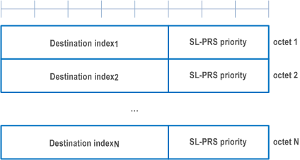
The SL-PRS Resource Request MAC CE is identified by a MAC subheader with eLCID as specified in Table 6.2.1-2b. It has the following fields:
- Destination index: The Destination Index field identifies the destination. The length of this field is 5 bits. The value is set to one index corresponding to SL destination identity associated to same destination reported in sl-PosTxResourceReqList if present. The value is indexed sequentially from 0 in the same ascending order of SL destination identity in sl-PosTxResourceReqList as specified in TS 38.331. When multiple lists are reported, the value is indexed sequentially across all the lists in the same order as presented in SidelinkUEInformaitonNR message;
- SL-PRS priority: Priority of pending SL-PRS transmission. The length of this field is 3 bits;
- SL-PRS Bandwidth: Requested minimum bandwidth of pending SL-PRS transmission. The length of this field is 5 bits. Encoding of this field is the same as sl-PRS-Bandwidth in IE SL-PRS-QoS-Info as specified in TS 38.331 that codepoint value 0 corresponds to the value "mhz5" of the field sl-PRS-Bandwidth, codepoint value 1 corresponds to the value "mhz10" of the field sl-PRS-Bandwidth, and so on;
- R: Reserved bit, set to 0.
6.1.3.75 LTM Cell Switch Command MAC CE |R18| p. 295
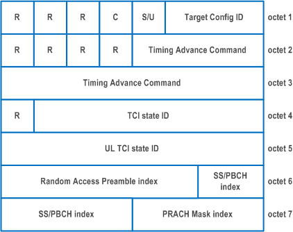
The LTM Cell Switch Command MAC CE is identified by MAC subheader with eLCID as specified in Table 6.2.1-1b. It has a variable size with following fields (Figure 6.1.3.75-1):
- R: Reserved bit, set to 0;
- Target Configuration ID: This field indicates the index of candidate target configuration to apply for LTM cell switch, corresponding to ltm-CandidateId minus 1 as specified in TS 38.331. The length of the field is 3 bits;
- Timing Advance Command: This field indicates whether the TA is valid for the LTM target cell (i.e. the SpCell corresponding to the target configuration indicated by Target Configuration ID field). If the value of this field is set to FFF, this field indicates that no valid timing adjustment is available for the PTAG of the LTM target cell; otherwise, this field indicates the index value TA used to control the amount of timing adjustment that the MAC entity has to apply in TS 38.213, and that the UE can skip the Random Access procedure for this LTM cell switch. If tag-Id-ptr is configured for the TCI state indicated by the UL TCI state ID field, if present, or by the TCI state ID field otherwise, in the LTM target cell and tag-Id-ptr is set to value n1, this field indicates the TA for the TAG indicated by the tag2-Id of the LTM target cell; otherwise, this field indicates the TA for the TAG indicated by the tag-id of the LTM target cell. The length of the field is 12 bits;
- TCI state ID: This field indicates and activates the TCI state for the LTM target cell (i.e. the SpCell of the target configuration indicated by the Target Configuration ID field). The TCI state is identified by TCI-StateId in ltm-DL-OrJointTCI-StateToAddModList as specified in TS 38.331. If the value of unifiedTCI-StateType in the ltm-TCI-Info of the configuration indicated by Target Configuration ID field is joint, this field is for joint TCI state, otherwise, this field is for downlink TCI state. The length of the field is 7 bits;
- UL TCI state ID: This field indicates and activates the uplink TCI state for the LTM target cell (i.e. the SpCell of the target configuration indicated by the Target Configuration ID field). The UL TCI state is identified by TCI-UL-StateId in ltm-UL-TCI-StateToAddModList as specified in TS 38.331. The octet containing this field (i.e. this field and the two reserved bits in the same octet) is included if the value of unifiedTCI-StateType in the ltm-TCI-Info of the configuration indicated by Target Configuration ID field is separate. The length of the field is 6 bits;
- C: This field indicates the presence of the contention-free Random Access Resources fields. If the value of this field is set to 1, the following fields are present: Random Access Preamble index field, S/U field, SS/PBCH index field, PRACH Mask index field, Repetition number field and the reserved bits in the same octet. If the value of this field is set to 0, these fields are absent.
- S/U: This field indicates which UL carrier to transmit the PRACH of the contention-free Random Access Resources. If the value of this field is set to 1, SUL is used; otherwise, NUL is used. The length of the field is 1 bit;
- Random Access Preamble index: This field indicates the Random Access Preamble index of the contention-free Random Access Resources. This field should not be set to 0b000000. The length of the field is 6 bits;
- SS/PBCH index: This field indicates the SS/PBCH that shall be used to determine the RACH occasion for the PRACH transmission of the contention-free Random Access Resources. The length of the field is 6 bits;
- PRACH Mask index: This field indicates the RACH occasion(s) associated with the SS/PBCH indicated by 'SS/PBCH index' for the PRACH transmission of the contention-free Random Access Resources. It indicates a subset of RACH occasion(s) from the rach-ConfigDedicated for the UL carrier (indicated by S/U field), (if provided, otherwise it indicates a subset of RACH occasion(s) from the rach-ConfigCommon for the UL carrier (indicated by S/U field) in the UL BWP configuration of firstActiveUplinkBWP-Id as specified in TS 38.331. When the repetition number field is not set to 0, the UE ignores this field. The length of the field is 4 bits;
- Repetition number: This field indicates the Msg1 repetition number to be applied to the contention-free Random Access. If this field is set to 0, Msg1 repetition number does not apply. If this field is set to 1, the Msg1 repetition number is 2. If this field is set to 2, the Msg1 repetition number is 4. If this field is set to 3, the Msg1 repetition number is 8. The length of the field is 2 bits.
6.1.3.76 Candidate Cell TCI States Activation/Deactivation MAC CE |R18| p. 297
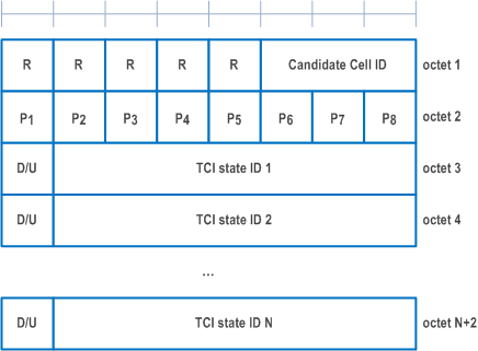
The Candidate Cell TCI States Activation/Deactivation MAC CE is identified by a MAC subheader with eLCID as specified in Table 6.2.1-1b. It has a variable size consisting of following fields:
- Candidate Cell ID: This field indicates the identity of an LTM candidate cell for which the MAC CE applies, corresponding to the ltm-CandidateId minus 1 as specified in TS 38.331. The length of the field is 3 bits;
- Pi: This field indicates whether each TCI codepoint has multiple TCI states or a single TCI state. If the Pi field is set to 1, the ith TCI codepoint includes the DL TCI state and the UL TCI state. If the Pi field is set to 0, the ith TCI codepoint includes only the DL/joint TCI state or the UL TCI state. The codepoint to which a TCI state is mapped is determined by its ordinal position among all the TCI state ID fields;
- D/U: This field indicates whether the TCI state ID in the same octet is for a joint/downlink or an uplink TCI state. If this field is set to 1, the TCI state ID in the same octet is for joint/downlink TCI state. If this field is set to 0, the TCI state ID in the same octet is for uplink TCI state;
- TCI state ID: This field indicates the TCI state identified by TCI-StateId in ltm-DL-OrJointTCI-StateToAddModList or TCI-UL-StateId in ltm-UL-TCI-StatesToAddModList as specified in TS 38.331. If D/U is set to 1, 7-bits length TCI state ID i.e. TCI-StateId as specified in TS 38.331 is used. If D/U is set to 0, the most significant bit of TCI state ID is considered as the reserved bit and remaining 6 bits indicate the TCI-UL-StateId as specified in TS 38.331. The maximum number of activated TCI states is 16;
- R: Reserved bit, set to 0.
6.1.3.77 Cross-RRH TCI State Indication for UE-specific PDCCH MAC CE |R18| p. 298
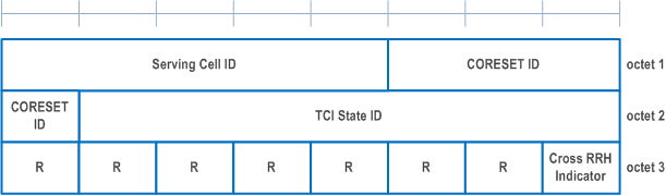
The Cross-RRH TCI State Indication for UE-specific PDCCH MAC CE is identified by a MAC subheader with eLCID as specified in Table 6.2.1-1b. It has a fixed size of 24 bits with following fields:
- Serving Cell ID: This field indicates the identity of the Serving Cell for which the MAC CE applies. The length of the field is 5 bits. If the indicated Serving Cell is configured as part of a simultaneousTCI-UpdateList1 or simultaneousTCI-UpdateList2 as specified in TS 38.331, this MAC CE applies to all the Serving Cells in the set simultaneousTCI-UpdateList1 or simultaneousTCI-UpdateList2, respectively;
- CORESET ID: This field indicates a Control Resource Set identified with ControlResourceSetId as specified in TS 38.331, for which the TCI State is being indicated. In case the value of the field is 0, the field refers to the Control Resource Set configured by controlResourceSetZero as specified in TS 38.331. The length of the field is 4 bits;
- TCI State ID: This field indicates the TCI state identified by TCI-StateId as specified in TS 38.331 applicable to the Control Resource Set identified by CORESET ID field. If the field of CORESET ID is set to 0, this field indicates a TCI-StateId for a TCI state of the first 64 TCI-states configured by tci-StatesToAddModList and tci-StatesToReleaseList in the PDSCH-Config in the active BWP. If the field of CORESET ID is set to the other value than 0, this field indicates a TCI-StateId configured by tci-StatesPDCCH-ToAddList and tci-StatesPDCCH-ToReleaseList in the controlResourceSet identified by the indicated CORESET ID. The length of the field is 7 bits;
- Cross RRH Indicator: This field indicates whether the lower layers follow TCI state switching delay requirements in high speed train FR2 scenarios and apply the one shot large UL timing adjustment after switching to a TCI state identified by TCI-StateId as specified in TS 38.331. The field is set to 1 to indicate that the lower layers apply the TCI state switching delay requirements specified in clause 8.10.3A of TS 38.133 and apply the one shot large timing adjustment requirements specified in clause 7.1.2.3 of TS 38.133 immediately to the first UL transmission after TCI state switch without checking the DL timing difference threshold. The field is set to 0 to indicate that the lower layers apply the TCI state switching delay requirements specified in clause 8.10.3 of TS 38.133 and apply the gradual timing adjustment requirements specified in clause 7.1.2.1 of TS 38.133 to the first UL transmission after TCI state switch without checking the DL timing difference threshold. The length of the field is 1 bit;
- R: Reserved bit, set to 0.
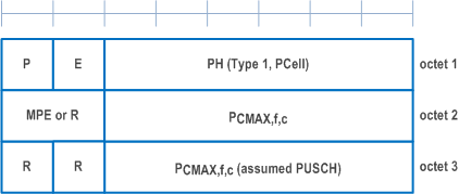
6.1.3.78 Single Entry PHR with assumed PUSCH MAC CE |R18| p. 299
The Single Entry PHR with assumed PUSCH MAC CE is identified by a MAC subheader with eLCID as specified in Table 6.2.1-2.
It has a variable size and consists of two or three octets defined as follows (Figure 6.1.3.8-1):
- R: Reserved bit, set to 0;
- Power Headroom (PH): This field indicates the power headroom level. The length of the field is 6 bits. The reported PH and the corresponding power headroom levels are shown in Table 6.1.3.8-1 below (the corresponding measured values in dB are specified in TS 38.133);
- E: This field indicates the presence of a PCMAX,f,c for assumed PUSCH field for PCell. The E field set to 1 indicates that a PCMAX,f,c for assumed PUSCH field for PCell is reported. The E field set to 0 indicates that a PCMAX,f,c for assumed PUSCH field for PCell is not reported;
- P: If mpe-Reporting-FR2 is configured and the Serving Cell operates on FR2, the MAC entity shall set this field to 0 if the applied P-MPR value, to meet MPE requirements, as specified in TS 38.101-2, is less than P-MPR_00 as specified in TS 38.133 and to 1 otherwise. If mpe-Reporting-FR2 is not configured or the Serving Cell operates on FR1, this field indicates whether power backoff is applied due to power management (as allowed by P-MPRc as specified in TS 38.101-1, TS 38.101-2, and TS 38.101-3). The MAC entity shall set the P field to 1 if the corresponding PCMAX,f,c field would have had a different value if no power backoff due to power management had been applied;
- PCMAX,f,c: This field indicates the PCMAX,f,c (as specified in TS 38.213) used for calculation of the preceding PH field. The reported PCMAX,f,c and the corresponding nominal UE transmit power levels are shown in Table 6.1.3.8-2 (the corresponding measured values in dBm are specified in TS 38.133);
- PCMAX,f,c for assumed PUSCH: This field indicates the PCMAX,f,c for assumed PUSCH(as specified in TS 38.213). The reported PCMAX,f,c and the corresponding nominal UE transmit power levels are shown in [Table 6.1.3.8-2] (the corresponding measured values in dBm are specified in TS 38.133);
- MPE: If mpe-Reporting-FR2 is configured, and the Serving Cell operates on FR2, and if the P field is set to 1, this field indicates the applied power backoff to meet MPE requirements, as specified in TS 38.101-2. This field indicates an index to Table 6.1.3.8-3 and the corresponding measured values of P-MPR levels in dB are specified in TS 38.133. The length of the field is 2 bits. If mpe-Reporting-FR2 is not configured, or if the Serving Cell operates on FR1, or if the P field is set to 0, R bits are present instead.
![]()
![]()
![]()