Content for TS 38.321 Word version: 18.3.0
1…
4…
5…
5.1.2…
5.2…
5.4…
5.4.4…
5.5…
5.9…
5.18…
5.18.18…
5.19…
5.22…
5.22.1.4…
5.22.2…
5.23…
6…
6.1.3…
6.1.3.8…
6.1.3.11…
6.1.3.17…
6.1.3.21…
6.1.3.26…
6.1.3.31…
6.1.3.37…
6.1.3.42…
6.1.3.49…
6.1.3.53…
6.1.3.59…
6.1.3.64…
6.1.3.70…
6.1.3.74…
6.1.3.79…
6.1.4…
6.2…
7…
6.1.3.11 Duplication Activation/Deactivation MAC CE
6.1.3.12 SP CSI-RS/CSI-IM Resource Set Activation/Deactivation MAC CE
6.1.3.13 Aperiodic CSI Trigger State Subselection MAC CE
6.1.3.14 TCI States Activation/Deactivation for UE-specific PDSCH MAC CE
6.1.3.15 TCI State Indication for UE-specific PDCCH MAC CE
6.1.3.16 SP CSI reporting on PUCCH Activation/Deactivation MAC CE
...
...
6.1.3.11 Duplication Activation/Deactivation MAC CE p. 229
The Duplication Activation/Deactivation MAC CE of one octet is identified by a MAC subheader with LCID as specified in Table 6.2.1-1. It has a fixed size and consists of a single octet containing eight D-fields. The Duplication Activation/Deactivation MAC CE is defined, for a MAC entity, as follows (Figure 6.1.3.11-1).
- Di: This field indicates the activation/deactivation status of the PDCP duplication of DRB i where i is the ascending order of the DRB ID among the DRBs configured with PDCP duplication and with RLC entity(ies) associated with this MAC entity. The Di field is set to 1 to indicate that the PDCP duplication of DRB i shall be activated. The Di field is set to 0 to indicate that the PDCP duplication of DRB i shall be deactivated.

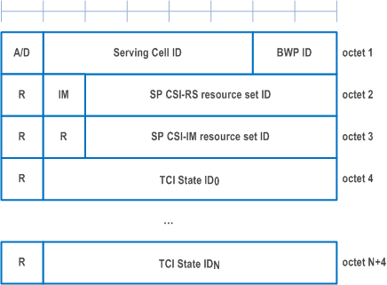
6.1.3.12 SP CSI-RS/CSI-IM Resource Set Activation/Deactivation MAC CE p. 229
The SP CSI-RS/CSI-IM Resource Set Activation/Deactivation MAC CE is identified by a MAC subheader with LCID as specified in Table 6.2.1-1. It has a variable size and consists of the following fields:
- A/D: This field indicates whether to activate or deactivate indicated SP CSI-RS and CSI-IM resource set(s). The field is set to 1 to indicate activation, otherwise it indicates deactivation;
- Serving Cell ID: This field indicates the identity of the Serving Cell for which the MAC CE applies. The length of the field is 5 bits;
- BWP ID: This field indicates a DL BWP for which the MAC CE applies as the codepoint of the DCI bandwidth part indicator field as specified in TS 38.212. The length of the BWP ID field is 2 bits;
- SP CSI-RS resource set ID: This field contains an index of NZP-CSI-RS-ResourceSet containing Semi Persistent NZP CSI-RS resources, as specified in TS 38.331, indicating the Semi Persistent NZP CSI-RS resource set, which shall be activated or deactivated. The length of the field is 6 bits;
- IM: This field indicates the presence of the octet containing SP CSI-IM resource set ID field. If the IM field is set to 1, the octet containing SP CSI-IM resource set ID field is present. If IM field is set to 0, the octet containing SP CSI-IM resource set ID field is not present;
- SP CSI-IM resource set ID: This field contains an index of CSI-IM-ResourceSet containing Semi Persistent CSI-IM resources, as specified in TS 38.331, indicating the Semi Persistent CSI-IM resource set, which shall be activated or deactivated. The length of the field is 6 bits;
- TCI State IDi: This field contains TCI-StateId, as specified in TS 38.331, of a TCI State, which is used as QCL source for the resource within the Semi Persistent NZP CSI-RS resource set indicated by SP CSI-RS resource set ID field. TCI State ID0 indicates TCI State for the first resource within the set, TCI State ID1 for the second one and so on. The length of the field is 7 bits. If the A/D field is set to 0, the octets containing TCI State ID field(s) are not present;
- R: Reserved bit, set to 0.

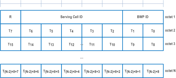
6.1.3.13 Aperiodic CSI Trigger State Subselection MAC CE p. 230
The Aperiodic CSI Trigger State Subselection MAC CE is identified by a MAC subheader with LCID as specified in Table 6.2.1-1. It has a variable size consisting of following fields:
- Serving Cell ID: This field indicates the identity of the Serving Cell for which the MAC CE applies. The length of the field is 5 bits;
- BWP ID: This field indicates a DL BWP for which the MAC CE applies as the codepoint of the DCI bandwidth part indicator field as specified in TS 38.212. The length of the BWP ID field is 2 bits;
- Ti: This field indicates the selection status of the Aperiodic Trigger States configured within aperiodicTriggerStateList, as specified in TS 38.331. T0 refers to the first trigger state within the list, T1 to the second one and so on. If the list does not contain entry with index i, MAC entity shall ignore the Ti field. The Ti field is set to 1 to indicate that the Aperiodic Trigger State i shall be mapped to the codepoint of the DCI CSI request field, as specified in TS 38.214. The codepoint to which the Aperiodic Trigger State is mapped is determined by its ordinal position among all the Aperiodic Trigger States with Ti field set to 1, i.e. the first Aperiodic Trigger State with Ti field set to 1 shall be mapped to the codepoint value 1, second Aperiodic Trigger State with Ti field set to 1 shall be mapped to the codepoint value 2 and so on. The maximum number of mapped Aperiodic Trigger States is 63;
- R: Reserved bit, set to 0.

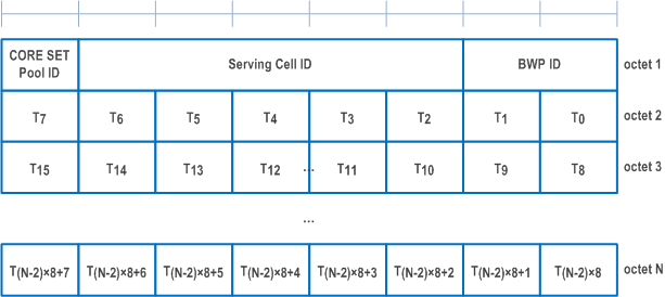
6.1.3.14 TCI States Activation/Deactivation for UE-specific PDSCH MAC CE p. 231
The TCI States Activation/Deactivation for UE-specific PDSCH MAC CE is identified by a MAC subheader with LCID as specified in Table 6.2.1-1. It has a variable size consisting of following fields:
- Serving Cell ID: This field indicates the identity of the Serving Cell for which the MAC CE applies. The length of the field is 5 bits. If the indicated Serving Cell is configured as part of a simultaneousTCI-UpdateList1 or simultaneousTCI-UpdateList2 as specified in TS 38.331, this MAC CE applies to all the Serving Cells configured in the set simultaneousTCI-UpdateList1 or simultaneousTCI-UpdateList2, respectively;
- BWP ID: This field indicates a DL BWP for which the MAC CE applies as the codepoint of the DCI bandwidth part indicator field as specified in TS 38.212. The length of the BWP ID field is 2 bits. This field is ignored if this MAC CE applies to a set of Serving Cells;
- Ti: If there is a TCI state with TCI-StateId i as specified in TS 38.331, this field indicates the activation/deactivation status of the TCI state with TCI-StateId i, otherwise MAC entity shall ignore the Ti field. The Ti field is set to 1 to indicate that the TCI state with TCI-StateId i shall be activated and mapped to the codepoint of the DCI Transmission Configuration Indication field, as specified in TS 38.214. The Ti field is set to 0 to indicate that the TCI state with TCI-StateId i shall be deactivated and is not mapped to the codepoint of the DCI Transmission Configuration Indication field. The codepoint to which the TCI State is mapped is determined by its ordinal position among all the TCI States with Ti field set to 1, i.e. the first TCI State with Ti field set to 1 shall be mapped to the codepoint value 0, second TCI State with Ti field set to 1 shall be mapped to the codepoint value 1 and so on. The maximum number of activated TCI states is 8. The activated TCI states can be associated with at most one PCI different from the Serving Cell PCI at a time;
- CORESET Pool ID: This field indicates that mapping between the activated TCI states and the codepoint of the DCI Transmission Configuration Indication set by field Ti is specific to the ControlResourceSetId configured with CORESET Pool ID as specified in TS 38.331. This field set to 1 indicates that this MAC CE shall be applied for the DL transmission scheduled by CORESET with the CORESET pool ID equal to 1, otherwise, this MAC CE shall be applied for the DL transmission scheduled by CORESET pool ID equal to 0. If the coresetPoolIndex is not configured for any CORESET, MAC entity shall ignore the CORESET Pool ID field in this MAC CE when receiving the MAC CE. If the Serving Cell in the MAC CE is configured in a cell list that contains more than one Serving Cell, the CORSET Pool ID field shall be ignored when receiving the MAC CE.

6.1.3.15 TCI State Indication for UE-specific PDCCH MAC CE p. 232
The TCI State Indication for UE-specific PDCCH MAC CE is identified by a MAC subheader with LCID as specified in Table 6.2.1-1. It has a fixed size of 16 bits with following fields:
- Serving Cell ID: This field indicates the identity of the Serving Cell for which the MAC CE applies. The length of the field is 5 bits. If the indicated Serving Cell is configured as part of a simultaneousTCI-UpdateList1 or simultaneousTCI-UpdateList2 as specified in TS 38.331, this MAC CE applies to all theServing Cells in the set simultaneousTCI-UpdateList1 or simultaneousTCI-UpdateList2, respectively;
- CORESET ID: This field indicates a Control Resource Set identified with ControlResourceSetId as specified in TS 38.331, for which the TCI State is being indicated. In case the value of the field is 0, the field refers to the Control Resource Set configured by controlResourceSetZero as specified in TS 38.331. The length of the field is 4 bits;
- TCI State ID: This field indicates the TCI state identified by TCI-StateId as specified in TS 38.331 applicable to the Control Resource Set identified by CORESET ID field. If the field of CORESET ID is set to 0, this field indicates a TCI-StateId for a TCI state of the first 64 TCI-states configured by tci-StatesToAddModList and tci-StatesToReleaseList in the PDSCH-Config in the active BWP or by dl-OrJoint-TCI-State-ToAddModList and dl-OrJoint-TCI-State-ToReleaseList in the PDSCH-Config in the active BWP or the reference BWP. If the field of CORESET ID is set to the other value than 0, this field indicates a TCI-StateId configured by tci-StatesPDCCH-ToAddList and tci-StatesPDCCH-ToReleaseList in the controlResourceSet identified by the indicated CORESET ID. The length of the field is 7 bits.

6.1.3.16 SP CSI reporting on PUCCH Activation/Deactivation MAC CE p. 232
The SP CSI reporting on PUCCH Activation/Deactivation MAC CE is identified by a MAC subheader with LCID as specified in Table 6.2.1-1. It has a fixed size of 16 bits with following fields:
- Serving Cell ID: This field indicates the identity of the Serving Cell for which the MAC CE applies. The length of the field is 5 bits;
- BWP ID: This field indicates a UL BWP for which the MAC CE applies as the codepoint of the DCI bandwidth part indicator field as specified in TS 38.212. The length of the BWP ID field is 2 bits;
- L: This field indciates whether the MAC CE applies to SP CSI reporting on PUCCH Activation/Deactivation for LTM or not. If ltm-CSI-ReportConfigToAddModList is not configured, R field is present instead (i.e. set to 0);
- Si: This field indicates the activation/deactivation status of the Semi-Persistent CSI report configuration within ltm-CSI-ReportConfigToAddModList if L field is set to 1, or csi-ReportConfigToAddModList if L field is set to 0, as specified in TS 38.331. S0 refers to the report configuration which includes PUCCH resources for SP CSI reporting in the indicated BWP and has the lowest CSI-ReportConfigId or LTM-CSI-ReportConfigId within the list with type set to semiPersistentOnPUCCH, S1 to the report configuration which includes PUCCH resources for SP CSI reporting in the indicated BWP and has the second lowest CSI-ReportConfigId or LTM-CSI-ReportConfigId and so on. If the number of report configurations within the list with type set to semiPersistentOnPUCCH in the indicated BWP is less than i + 1, MAC entity shall ignore the Si field. The Si field is set to 1 to indicate that the corresponding Semi-Persistent CSI report configuration shall be activated. The Si field is set to 0 to indicate that the corresponding Semi-Persistent CSI report configuration i shall be deactivated. If the Semi-Persistent CSI report configuration i is configured with csi-ReportSubConfigToAddModList, the Si field is set to 0 to additionally indicate that all sub-configurations within csi-ReportSubConfigToAddModList shall be deactivated;
- R: Reserved bit, set to 0.
