Content for TS 38.321 Word version: 18.3.0
1…
4…
5…
5.1.2…
5.2…
5.4…
5.4.4…
5.5…
5.9…
5.18…
5.18.18…
5.19…
5.22…
5.22.1.4…
5.22.2…
5.23…
6…
6.1.3…
6.1.3.8…
6.1.3.11…
6.1.3.17…
6.1.3.21…
6.1.3.26…
6.1.3.31…
6.1.3.37…
6.1.3.42…
6.1.3.49…
6.1.3.53…
6.1.3.59…
6.1.3.64…
6.1.3.70…
6.1.3.74…
6.1.3.79…
6.1.4…
6.2…
7…
6.1.3.17 SP SRS Activation/Deactivation MAC CE
6.1.3.18 PUCCH spatial relation Activation/Deactivation MAC CE
6.1.3.19 SP ZP CSI-RS Resource Set Activation/Deactivation MAC CE
6.1.3.20 Recommended bit rate MAC CE
...
...
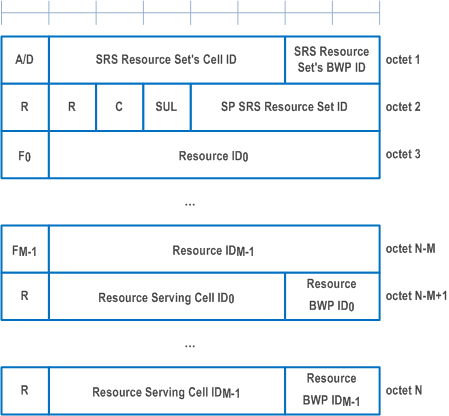
6.1.3.17 SP SRS Activation/Deactivation MAC CE p. 233
The SP SRS Activation/Deactivation MAC CE is identified by a MAC subheader with LCID as specified in Table 6.2.1-1. It has a variable size with following fields:
- A/D: This field indicates whether to activate or deactivate indicated SP SRS resource set. The field is set to 1 to indicate activation, otherwise it indicates deactivation;
- SRS Resource Set's Cell ID: This field indicates the identity of the Serving Cell, which contains activated/deactivated SP SRS Resource Set. If the C field is set to 0, this field also indicates the identity of the Serving Cell which contains all resources indicated by the Resource IDi fields. The length of the field is 5 bits;
- SRS Resource Set's BWP ID: This field indicates a UL BWP as the codepoint of the DCI bandwidth part indicator field as specified in TS 38.212, which contains activated/deactivated SP SRS Resource Set. If the C field is set to 0, this field also indicates the identity of the BWP which contains all resources indicated by the Resource IDi fields. The length of the field is 2 bits;
- C: This field indicates whether the octets containing Resource Serving Cell ID field(s) and Resource BWP ID field(s) are present. If this field is set to 1, the octets containing Resource Serving Cell ID field(s) and Resource BWP ID field(s) are present, otherwise they are not present;
- SUL: This field indicates whether the MAC CE applies to the NUL carrier or SUL carrier configuration. This field is set to 1 to indicate that it applies to the SUL carrier configuration, and it is set to 0 to indicate that it applies to the NUL carrier configuration;
- SP SRS Resource Set ID: This field indicates the SP SRS Resource Set ID identified by SRS-ResourceSetId as specified in TS 38.331, which is to be activated or deactivated. The length of the field is 4 bits;
- Fi: This field indicates the type of a resource used as a spatial relationship for SRS resource within SP SRS Resource Set indicated with SP SRS Resource Set ID field. F0 refers to the first SRS resource within the resource set, F1 to the second one and so on. The field is set to 1 to indicate NZP CSI-RS resource index is used, and it is set to 0 to indicate either SSB index or SRS resource index is used. The length of the field is 1 bit. This field is only present if MAC CE is used for activation, i.e. the A/D field is set to 1;
- Resource IDi: This field contains an identifier of the resource used for spatial relationship derivation for SRS resource i. Resource ID0 refers to the first SRS resource within the resource set, Resource ID1 to the second one and so on. If Fi is set to 0, and the first bit of this field is set to 1, the remainder of this field contains SSB-Index as specified in TS 38.331. If Fi is set to 0, and the first bit of this field is set to 0, the remainder of this field contains SRS-ResourceId as specified in TS 38.331. The length of the field is 7 bits. This field is only present if MAC CE is used for activation, i.e. the A/D field is set to 1;
- Resource Serving Cell IDi: This field indicates the identity of the Serving Cell on which the resource used for spatial relationship derivation for SRS resource i is located. The length of the field is 5 bits;
- Resource BWP IDi: This field indicates a UL BWP as the codepoint of the DCI bandwidth part indicator field as specified in TS 38.212, on which the resource used for spatial relationship derivation for SRS resource i is located. The length of the field is 2 bits;
- R: Reserved bit, set to 0.

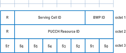
6.1.3.18 PUCCH spatial relation Activation/Deactivation MAC CE p. 234
The PUCCH spatial relation Activation/Deactivation MAC CE is identified by a MAC subheader with LCID as specified in Table 6.2.1-1. It has a fixed size of 24 bits with following fields:
- Serving Cell ID: This field indicates the identity of the Serving Cell for which the MAC CE applies. The length of the field is 5 bits;
- BWP ID: This field indicates a UL BWP for which the MAC CE applies as the codepoint of the DCI bandwidth part indicator field as specified in TS 38.212. The length of the BWP ID field is 2 bits;
- PUCCH Resource ID: This field contains an identifier of the PUCCH resource ID identified by PUCCH-ResourceId as specified in TS 38.331. The length of the field is 7 bits;
- Si: If, in PUCCH-Config in which the PUCCH Resource ID is configured, there is a PUCCH Spatial Relation Info with PUCCH-SpatialRelationInfoId as specified in TS 38.331, configured for the uplink bandwidth part indicated by BWP ID field, Si indicates the activation status of PUCCH Spatial Relation Info with PUCCH-SpatialRelationInfoId equal to i + 1, otherwise MAC entity shall ignore this field. The Si field is set to 1 to indicate PUCCH Spatial Relation Info with PUCCH-SpatialRelationInfoId equal to i + 1 shall be activated. The Si field is set to 0 to indicate PUCCH Spatial Relation Info with PUCCH-SpatialRelationInfoId equal to i + 1 shall be deactivated. Only a single PUCCH Spatial Relation Info can be active for a PUCCH Resource at a time;
- R: Reserved bit, set to 0.

6.1.3.19 SP ZP CSI-RS Resource Set Activation/Deactivation MAC CE p. 235
The SP ZP CSI-RS Resource Set Activation/Deactivation MAC CE is identified by a MAC subheader with LCID as specified in Table 6.2.1-1. It has a fixed size of 16 bits with following fields:
- A/D: This field indicates whether to activate or deactivate indicated SP ZP CSI-RS resource set. The field is set to 1 to indicate activation, otherwise it indicates deactivation;
- Serving Cell ID: This field indicates the identity of the Serving Cell for which the MAC CE applies. The length of the field is 5 bits;
- BWP ID: This field indicates a DL BWP for which the MAC CE applies as the codepoint value of the DCI bandwidth part indicator field as specified in TS 38.212. The length of the BWP ID field is 2 bits;
- SP ZP CSI-RS resource set ID: This field contains an index of sp-ZP-CSI-RS-ResourceSetsToAddModList, as specified in TS 38.331, indicating the Semi Persistent ZP CSI-RS resource set, which shall be activated or deactivated. The length of the field is 4 bits;
- R: Reserved bit, set to 0.

6.1.3.20 Recommended bit rate MAC CE p. 235
The Recommended bit rate MAC CE is identified by a MAC subheader with LCID as specified in Table 6.2.1-1 and Table 6.2.1-2 for bit rate recommendation message from the gNB to the UE and bit rate recommendation query message from the UE to the gNB, respectively. It has a fixed size and consists of two octets defined as follows (Figure 6.1.3.20-1):
- LCID: This field indicates the identity of the logical channel for which the recommended bit rate or the recommended bit rate query is applicable. The length of the field is 6 bits;
- Uplink/Downlink (UL/DL): This field indicates whether the recommended bit rate or the recommended bit rate query applies to uplink or downlink. The length of the field is 1 bit. The UL/DL field set to 0 indicates downlink. The UL/DL field set to 1 indicates uplink;
- Bit Rate: This field indicates an index to Table 6.1.3.20-1. The length of the field is 6 bits. For bit rate recommendation the value indicates the recommended bit rate. For bit rate recommendation query the value indicates the desired bit rate;
- X: Bit rate multiplier. For UEs supporting recommended bit rate multiplier, when bitRateMultiplier is configured for the logical channel indicated by LCID field, X field set to 1 indicates the actual value of bit rate is the value corresponding to the index indicated by the Bit Rate field multiplied by bitRateMultiplier as specified in TS 38.331.
- R: reserved bit, set to 0.

| Index | NR Recommended Bit Rate value [kbit/s] | Index | NR Recommended Bit Rate value [kbit/s] |
|---|---|---|---|
| 0 | Note 1 | 32 | 700 |
| 1 | 0 | 33 | 800 |
| 2 | 9 | 34 | 900 |
| 3 | 11 | 35 | 1000 |
| 4 | 13 | 36 | 1100 |
| 5 | 17 | 37 | 1200 |
| 6 | 21 | 38 | 1300 |
| 7 | 25 | 39 | 1400 |
| 8 | 29 | 40 | 1500 |
| 9 | 32 | 41 | 1750 |
| 10 | 36 | 42 | 2000 |
| 11 | 40 | 43 | 2250 |
| 12 | 48 | 44 | 2500 |
| 13 | 56 | 45 | 2750 |
| 14 | 72 | 46 | 3000 |
| 15 | 88 | 47 | 3500 |
| 16 | 104 | 48 | 4000 |
| 17 | 120 | 49 | 4500 |
| 18 | 140 | 50 | 5000 |
| 19 | 160 | 51 | 5500 |
| 20 | 180 | 52 | 6000 |
| 21 | 200 | 53 | 6500 |
| 22 | 220 | 54 | 7000 |
| 23 | 240 | 55 | 7500 |
| 24 | 260 | 56 | 8000 |
| 25 | 280 | 57 | Reserved |
| 26 | 300 | 58 | Reserved |
| 27 | 350 | 59 | Reserved |
| 28 | 400 | 60 | Reserved |
| 29 | 450 | 61 | Reserved |
| 30 | 500 | 62 | Reserved |
| 31 | 600 | 63 | Reserved |
|
NOTE 1:
For bit rate recommendation message this index is used for indicating that no new recommendation on bit rate is given.
|
|||