Content for TS 38.321 Word version: 18.3.0
1…
4…
5…
5.1.2…
5.2…
5.4…
5.4.4…
5.5…
5.9…
5.18…
5.18.18…
5.19…
5.22…
5.22.1.4…
5.22.2…
5.23…
6…
6.1.3…
6.1.3.8…
6.1.3.11…
6.1.3.17…
6.1.3.21…
6.1.3.26…
6.1.3.31…
6.1.3.37…
6.1.3.42…
6.1.3.49…
6.1.3.53…
6.1.3.59…
6.1.3.64…
6.1.3.70…
6.1.3.74…
6.1.3.79…
6.1.4…
6.2…
7…
6.1.3.21 Timing Delta MAC CE
6.1.3.22 Guard Symbols MAC CEs
6.1.3.23 BFR MAC CEs
6.1.3.24 Enhanced TCI States Activation/Deactivation for UE-specific PDSCH MAC CE
6.1.3.25 Enhanced PUCCH Spatial Relation Activation/Deactivation MAC CE
...
...
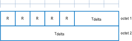
6.1.3.21 Timing Delta MAC CE |R16| p. 236
The Timing Delta MAC CE is identified by MAC subheader with eLCID as specified in Table 6.2.1-1b.
It has a fixed size and consists of two octets defined as follows (Figure 6.1.3.21-1):
- R: Reserved bit, set to 0;
- Tdelta: This field indicates the value (0, 1, …, 2047) used to control the amount of timing adjustment that MAC entity indicates (as specified in TS 38.213). The length of the field is 11 bits.
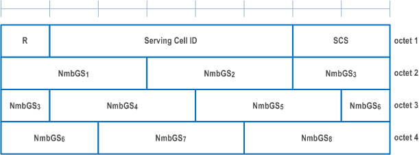
6.1.3.22 Guard Symbols MAC CEs |R16| p. 237
The Guard Symbols MAC CEs (i.e. Provided Guard Symbols MAC CE and Desired Guard Symbols MAC CE) for Case-1 timing mode are identified by the MAC subheader with eLCID as specified in Table 6.2.1-1b for DL-SCH and in Table 6.2.1-2b for UL-SCH.
It has fixed size and consists of four octets defined as follows (Figure 6.1.3.22-1):
- R: Reserved bit, set to 0;
- Serving Cell ID: This field indicates the identity of the Serving Cell for which the MAC CE applies. The length of the field is 5 bits;
- Sub-carrier spacing (SCS): This field indicates the subcarrier spacing used as reference for the guard spacing. The length of this field is 2bits. The values for the SCS field are shown in Table 6.1.3.22-2;
- Number of Guard Symbols (NmbGSi): This field indicates the number of guard symbols for the switching scenarios shown in Table 5.18.19-1. The number of guard symbols can take values within the range of 0 to 4. Higher values 5 to 7 are reserved.
| Subcarrier spacing | SCS value |
|---|---|
| 15kHz | 00 |
| 30kHz | 01 |
| 60kHz | 10 |
| 120kHz | 11 |
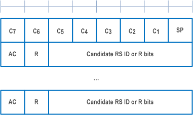
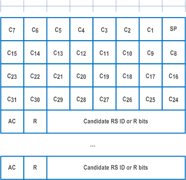
6.1.3.23 BFR MAC CEs |R16| p. 238
The MAC CEs for BFR consists of either:
- BFR MAC CE; or
- Truncated BFR MAC CE.
- the highest ServCellIndex of this MAC entity's SCell for which beam failure is detected and the evaluation of the candidate beams according to the requirements as specified in TS 38.133 has been completed is less than 8; or
- beam failure is detected for SpCell (as specified in clause 5.17) and the SpCell is to be indicated in a Truncated BFR MAC CE and the UL-SCH resources available for transmission cannot accommodate the Truncated BFR MAC CE with the four octets bitmap plus its subheader as a result of LCP.
- SP: This field indicates beam failure detection (as specified in clause 5.17) for the SpCell of this MAC entity. The SP field is set to 1 to indicate that beam failure is detected for SpCell only when BFR MAC CE or Truncated BFR MAC CE is to be included into a MAC PDU as part of Random Access Procedure (as specified in clause 5.1.3a and clause 5.1.4), otherwise, it is set to 0;
- Ci (BFR MAC CE): This field indicates beam failure detection (as specified in clause 5.17) and the presence of an octet containing the AC field for the SCell with ServCellIndex i as specified in TS 38.331. The Ci field set to 1 indicates that beam failure is detected, the evaluation of the candidate beams according to the requirements as specified in TS 38.133 has been completed, and the octet containing the AC field is present for the SCell with ServCellIndex i. The Ci field set to 0 indicates that the beam failure is either not detected or the beam failure is detected but the evaluation of the candidate beams according to the requirements as specified in TS 38.133 has not been completed, and the octet containing the AC field is not present for the SCell with ServCellIndex i. The octets containing the AC field are present in ascending order based on the ServCellIndex;
- Ci (Truncated BFR MAC CE): This field indicates beam failure detection (as specified in clause 5.17) for the SCell with ServCellIndex i as specified in TS 38.331. The Ci field set to 1 indicates that beam failure is detected, the evaluation of the candidate beams according to the requirements as specified in TS 38.133 has been completed, and the octet containing the AC field for the SCell with ServCellIndex i may be present. The Ci field set to 0 indicates that the beam failure is either not detected or the beam failure is detected but the evaluation of the candidate beams according to the requirements as specified in TS 38.133 has not been completed, and the octet containing the AC field is not present for the SCell with ServCellIndex i. The octets containing the AC field, if present, are included in ascending order based on the ServCellIndex. The number of octets containing the AC field included is maximised, while not exceeding the available grant size;
- AC: This field indicates the presence of the Candidate RS ID field in this octet. If at least one of the SSBs with SS-RSRP above rsrp-ThresholdBFR amongst the SSBs in candidateBeamRSSCellList or the CSI-RSs with CSI-RSRP above rsrp-ThresholdBFR amongst the CSI-RSs in candidateBeamRSSCellList is available, the AC field is set to 1; otherwise, it is set to 0. If the AC field set to 1, the Candidate RS ID field is present. If the AC field set to 0, R bits are present instead;
- Candidate RS ID: This field is set to the index of an SSB with SS-RSRP above rsrp-ThresholdBFR amongst the SSBs in candidateBeamRSSCellList or to the index of a CSI-RS with CSI-RSRP above rsrp-ThresholdBFR amongst the CSI-RSs in candidateBeamRSSCellList. Index of an SSB or CSI-RS is the index of an entry in candidateBeamRSSCellList corresponding to the SSB or CSI-RS. Index 0 corresponds to the first entry in the candidateBeamRSSCellList, index 1 corresponds to the second entry in the list and so on. The length of this field is 6 bits.
- R: Reserved bit, set to 0.
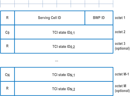
6.1.3.24 Enhanced TCI States Activation/Deactivation for UE-specific PDSCH MAC CE |R16| p. 239
The Enhanced TCI States Activation/Deactivation for UE-specific PDSCH MAC CE is identified by a MAC PDU subheader with eLCID as specified in Table 6.2.1-1b. It has a variable size consisting of following fields:
- Serving Cell ID: This field indicates the identity of the Serving Cell for which the MAC CE applies. The length of the field is 5 bits. If the indicated Serving Cell is configured as part of a simultaneousTCI-UpdateList1 or simultaneousTCI-UpdateList2 as specified in TS 38.331, this MAC CE applies to all the Serving Cells configured in the set simultaneousTCI-UpdateList1 or simultaneousTCI-UpdateList2, respectively;
- BWP ID: This field indicates a DL BWP for which the MAC CE applies as the codepoint of the DCI bandwidth part indicator field as specified in TS 38.212. The length of the BWP ID field is 2 bits;
- Ci: This field indicates whether the octet containing TCI state IDi,2 is present. If this field is set to 1, the octet containing TCI state IDi,2 is present. If this field is set to 0, the octet containing TCI state IDi,2 is not present;
- TCI state IDi,j: This field indicates the TCI state identified by TCI-StateId as specified in TS 38.331, where i is the index of the codepoint of the DCI Transmission configuration indication field as specified in TS 38.212 and TCI state IDi,j denotes the jth TCI state indicated for the ith codepoint in the DCI Transmission Configuration Indication field. The TCI codepoint to which the TCI States are mapped is determined by its ordinal position among all the TCI codepoints with sets of TCI state IDi,j fields, i.e. the first TCI codepoint with TCI state ID0,1 and TCI state ID0,2 shall be mapped to the codepoint value 0, the second TCI codepoint with TCI state ID1,1 and TCI state ID1,2 shall be mapped to the codepoint value 1 and so on. The TCI state IDi,2 is optional based on the indication of the Ci field. The maximum number of activated TCI codepoint is 8 and the maximum number of TCI states mapped to a TCI codepoint is 2.
- R: Reserved bit, set to 0.
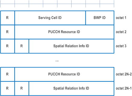
6.1.3.25 Enhanced PUCCH Spatial Relation Activation/Deactivation MAC CE |R16| p. 240
The Enhanced PUCCH Spatial Relation Activation/Deactivation MAC CE is identified by a MAC subheader with eLCID as specified in Table 6.2.1-1b. It has a variable size with following fields:
- Serving Cell ID: This field indicates the identity of the Serving Cell for which the MAC CE applies. The length of the field is 5 bits;
- BWP ID: This field indicates a UL BWP for which the MAC CE applies as the codepoint of the DCI bandwidth part indicator field as specified in TS 38.212. The length of the BWP ID field is 2 bits;
- PUCCH Resource ID: This field contains an identifier of the PUCCH resource ID identified by PUCCH-ResourceId as specified in TS 38.331, which is to be activated with a spatial relation indicated by Spatial Relation Info ID field in the subsequent octet. The length of the field is 7 bits. If the indicated PUCCH Resource ID is included in a PUCCH Resource Group (configured via resourceGroupToAddModList as specified in TS 38.331) of the indicated UL BWP, no other PUCCH Resources within the same PUCCH Resource group are indicated in the MAC CE, and this MAC CE applies to all the PUCCH Resources in the PUCCH Resource group;
- Spatial Relation Info ID: This field contains PUCCH-SpatialRelationInfoId - 1 where PUCCH-SpatialRelationInfoId is the identifier of the PUCCH Spatial Relation Info in PUCCH-Config in which the PUCCH Resource ID is configured, as specified in TS 38.331. The length of the field is 6 bits;
- R: Reserved bit, set to 0.
![]()
![]()
![]()