Content for TS 38.321 Word version: 18.3.0
1…
4…
5…
5.1.2…
5.2…
5.4…
5.4.4…
5.5…
5.9…
5.18…
5.18.18…
5.19…
5.22…
5.22.1.4…
5.22.2…
5.23…
6…
6.1.3…
6.1.3.8…
6.1.3.11…
6.1.3.17…
6.1.3.21…
6.1.3.26…
6.1.3.31…
6.1.3.37…
6.1.3.42…
6.1.3.49…
6.1.3.53…
6.1.3.59…
6.1.3.64…
6.1.3.70…
6.1.3.74…
6.1.3.79…
6.1.4…
6.2…
7…
6.1.3.64 Desired IAB-MT PSD range MAC CE
6.1.3.65 Timing Case Indication MAC CE
6.1.3.66 NCR Downlink Backhaul Link Beam Indication MAC CE
6.1.3.67 NCR Uplink Backhaul Link Beam Indication MAC CE
6.1.3.68 NCR Access Link Beam Indication MAC CE
6.1.3.69 SL LBT failure MAC CEs
...
...
6.1.3.64 Desired IAB-MT PSD range MAC CE |R17| p. 287
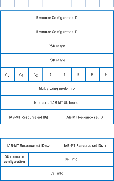
The Desired IAB-MT PSD range MAC CE is identified by MAC subheader with eLCID as specified in Table 6.2.1-2b. It has a variable size with following fields (Figure 6.1.3.64-1):
- Resource Configuration ID: This field indicates the RRC configuration which applies to this MAC CE and corresponds to iab-ResourceConfigID parameter in IAB-ResourceConfig as specified in TS 38.331. The length of the field is 16 bits;
- PSD range: This field contains the desired PSD range a node sends to its parent node to help with the sending node's MT UL TX power control. The desired PSD range is indicated by a maximum value (i.e. Pmax), and an offset relative to the maximum value, i.e. the desired PSD range is from Pmax - offset to Pmax. The 4 left-most bits of the field indicate the offset, the offset range is from 0 dB to 10 dB, the value 0000 corresponds to 0 dB, the value 0001 corresponds to 1 dB and so on, the values from 1011 onwards are reserved. The next 7 left-most bits indicate the Pmax range, the Pmax range is from -60 dBm to 50 dBm, the value 0000000 corresponds to -60 dBm, the value 0000001 corresponds to -59 dBm and so on, the values from 1101111 onwards are reserved. The remaining 5 bits are set to zero. The length of the field is 16 bits;
- C0: This field indicates whether the octet containing multiplexing mode info (containing the Multiplexing mode info field) is included or not. The field is set to 1 to indicate that multiplexing mode info is included, and it is set to 0 to indicate that multiplexing mode info is not present. The length of the field is 1 bit;
- C1: This field indicates whether the two octets containing the Cell info are included or not. The field is set to 0 to indicate the two octets are not included (and subsequently, that no cell information is included). The field is set to 1 to indicate that the two octets are included. The length of the field is 1 bits;
- C2: This field indicates whether any information on IAB-MT UL beams is included or not. The field is set to 1 to indicate that at least one IAB-MT Resource set IDi field is included, and it is set to 0 to indicate that no IAB-MT Resource set IDi field is present. The length of the field is 1 bit;
- R: Reserved bit, set to 0;
- Multiplexing mode info: The two rightmost bits indicate which of the four multiplexing modes defined in TS 38.473 is applicable. The third rightmost bit of this field indicates whether multiplexing restrictions mode information contained in the two rightmost bits of the field are applicable to non-overlapping frequency resources. This bit is set to 1 when multiplexing mode information contained in the two rightmost bits of the Multiplexing mode info field is applicable to non-overlapping frequency resources. This field is set to 0 when multiplexing mode information contained in the two rightmost bits of the Multiplexing mode info field is not applicable to non-overlapping frequency resources. The remaining 5 bits of this field are set to zero. The length of the field is 8 bits;
- Number of IAB-MT UL beams: This field indicates the number N of IAB-MT UL beams included in the MAC CE. The length of the field is 8 bits;
- IAB-MT Resource set IDi: an indication of the IAB-MTs uplink beams. IAB-MT Resource set ID0 field refers to the first IAB-MT uplink beam, IAB-MT Resource set ID1 field refers to the second IAB-MT uplink beam, and so on. If the total number N of beams included in the MAC CE is odd, the 4 right-most bits in the final octet of the IAB-MT Resource set are disregarded by the UE. The length of the field is 4 bits;
- DU resource configuration: when this field is set to 00, the provided power adjustment is applied on FDM resources where the simultaneous MT and DU signals are non-overlapping in the frequency-domain; when this field is set to 01, the provided power adjustment is applied on non-FDM resources where the simultaneous MT and DU signals may overlap in the frequency-domain for a given (MT CC, DU cell); when this field is set to 10, the provided power adjustment is applied on FDM resources where the simultaneous MT and DU signals are non-overlapping in the frequency-domain, and on non-FDM resources where the simultaneous MT and DU signals may overlap in the frequency-domain for a given (MT CC, DU cell). The length of the field is 2 bits;
- Cell info: indicates the cell configuration associated with the information contained in the MAC CE. IAB-DU cell is contained in the first nine bits of the field, while the Child IAB-MT Serving Cell index into the next 5 bits of the field. The length of the field is 14 bits.

6.1.3.65 Timing Case Indication MAC CE |R17| p. 289
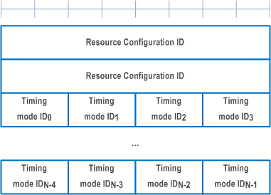
The Timing Case Indication MAC CE is identified by MAC subheader with eLCID as specified in Table 6.2.1-1b. It has a variable size with following fields (Figure 6.1.3.65-1):
- Resource Configuration ID: This field indicates the RRC configuration which applies to this MAC CE and corresponds to iab-ResourceConfigID parameter in IAB-ResourceConfig as specified in TS 38.331. The length of the field is 16 bits;
- Timing mode IDi: when this field is set to 00, the timing mode applied to the ith slot in the list of slots slotList provided via RRC in IAB-ResourceConfig is Case-1; when this field is set to 01, the timing mode applied to the ith slot in the list of slots slotList provided via RRC in IAB-ResourceConfig is Case-6; when this field is set to 10, the timing mode applied to the ith slot in the list of slots slotList provided via RRC in IAB-ResourceConfig is Case-7. The total number N of Timing mode IDi fields corresponds to the size of slotList provided via RRC in IAB-ResourceConfig. If number N is not divisible by 4, (4 - N mod 4) of the final Timing mode IDi fields are disregarded by the receiving IAB node. The length of the field is 2 bits.

6.1.3.66 NCR Downlink Backhaul Link Beam Indication MAC CE |R18| p. 290
The NCR Downlink Backhaul Link Beam Indication MAC CE is identified by MAC subheader with eLCID as specified in Table 6.2.1-1b. It has a fixed size and consists of a single octet defined as follows (Figure 6.1.3.66-1):
- Downlink TCI state ID: This field is used to indicate the downlink beam to be used for backhaul link transmission. It contains TCI-StateId (comprising all 7 bits), as specified in TS 38.331, of a TCI State in the active DL BWP. The length of the field is 7 bits;
- R: Reserved bit, set to 0.

6.1.3.67 NCR Uplink Backhaul Link Beam Indication MAC CE |R18| p. 290
The NCR Uplink Backhaul Link Beam Indication MAC CE is identified by MAC subheader with eLCID as specified in Table 6.2.1-1b. It has a fixed size and consists of a single octet defined as follows (Figure 6.1.3.67-1):
- Uplink TCI state ID or SRS Resource ID: This field is used to indicate the uplink beam to be used for backhaul link transmission. If the dl-OrJointTCI-StateList is configured as specified in TS 38.331 and unifiedTCI-StateType is configured with a value joint, this field contains TCI-StateId (comprising all 7 bits) of a Joint TCI State configured in the active DL BWP, which is used as the uplink beam indication for backhaul link transmission. If the ul-TCI-StateList is configured as specified in TS 38.331, this field contains TCI-UL-State-Id (contained in the 6 rightmost bits) of an UL TCI State configured in the active UL BWP, which is used as the uplink beam indication for backhaul link transmission, with the 1 remaining bit set to zero. Otherwise, 6 rightmost bits of this field contain SRS-ResourceID configured in the active UL BWP which is used as the uplink beam indication for backhaul link transmission, with the 1 remaining bit set to zero;
- R: Reserved bit, set to 0.

6.1.3.68 NCR Access Link Beam Indication MAC CE |R18| p. 291
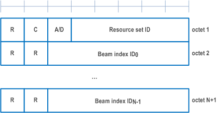
The NCR Access Link Beam Indication MAC CE is identified by MAC subheader with eLCID as specified in Table 6.2.1-1b. It has a variable size and consists of the following fields (Figure 6.1.3.68-1):
- Resource set ID: This field is used to indicate one of forwarding semi-persistent resource lists signalled in NCR-SemiPersistentFwdResourceSet (as specified in TS 38.331). The field contains a list ID (comprising all 5 bits);
- A/D: If the value of this field is set to 1, the forwarding resource list indicated in Resource set ID field is being activated. If the value of this field is set to 0, the forwarding resource list indicated in Resource set ID field is being deactivated;
- C: If the value of this field is set to 1, the Beam index IDi field is present. If the value of this field is set to 0, the Beam index IDi field is absent. This field can be set to 1 only if MAC CE is used for activation, i.e., when the A/D field is set to 1. If MAC CE is used for deactivation, this field is set to 0;
- Beam index IDi: This field indicates the updated beam index for forwarding resources within the list indicated by the Resource set ID field. Beam index ID0 indicates the beam index for the first forwarding resource within the list; Beam index ID1 indicates the beam index for the second forwarding resource within the list and so on. The length of the field is 6 bits; the number of updated beams, N, is equal to the number of the beam indications in the semi-persistent resource set with ID Resource set ID;
- R: Reserved bit, set to 0.

6.1.3.69 SL LBT failure MAC CEs |R18| p. 291
The SL LBT failure MAC CE of one octet is identified by a MAC subheader with LCID as specified in Table 6.2.1-2. It has a fixed size of 8bits. The priority of the Sidelink LBT failure MAC CE is fixed to '1':
- Ri: If there is a RB set configured for the MAC entity with RB set index i as specified in TS 38.214 and if Sidelink consistent LBT failure have been triggered and not cancelled in this RB set, the field is set to 1, otherwise the field is set to 0;
- R: Reserved bit, set to 0.
