Content for TS 38.321 Word version: 18.3.0
1…
4…
5…
5.1.2…
5.2…
5.4…
5.4.4…
5.5…
5.9…
5.18…
5.18.18…
5.19…
5.22…
5.22.1.4…
5.22.2…
5.23…
6…
6.1.3…
6.1.3.8…
6.1.3.11…
6.1.3.17…
6.1.3.21…
6.1.3.26…
6.1.3.31…
6.1.3.37…
6.1.3.42…
6.1.3.49…
6.1.3.53…
6.1.3.59…
6.1.3.64…
6.1.3.70…
6.1.3.74…
6.1.3.79…
6.1.4…
6.2…
7…
6.1.3.31 Multiple Entry Configured Grant Confirmation MAC CE
6.1.3.32 Duplication RLC Activation/Deactivation MAC CE
6.1.3.33 Sidelink Buffer Status Report MAC CEs
6.1.3.34 Sidelink Configured Grant Confirmation MAC CE
6.1.3.35 Sidelink CSI Reporting MAC CE
6.1.3.36 SP Positioning SRS Activation/Deactivation MAC CE
...
...
6.1.3.31 Multiple Entry Configured Grant Confirmation MAC CE |R16| p. 246
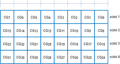
The Multiple Entry Configured Grant Confirmation MAC CE is identified by a MAC subheader with eLCID as specified in Table 6.2.1-2b. It has a fixed size and consists of a four octets containing 32 CG-fields. The Multiple Entry Configured Grant Confirmation MAC CE is defined as follows (Figure 6.1.3.31-1).
-
CGi: This field indicates whether PDCCH indicating activation or deactivation of configured uplink grant with Configured
Grant Config Index MAC i has been received. The CGi field is set to 1 to indicate that PDCCH indicating activation or deactivation of type 2 configured uplink grant with Configured Grant Config Index MAC i has been received. The CGi field is set to 0 to indicate that PDCCH indicating activation or deactivation of type 2 configured uplink grant with Configured Grant Config Index MAC i has not been received.
6.1.3.32 Duplication RLC Activation/Deactivation MAC CE |R16| p. 246
The Duplication RLC Activation/Deactivation MAC CE is identified by a MAC subheader with eLCID as specified in Table 6.2.1-1b. It has a fixed size and consists of a single octet defined as follows (Figure 6.1.3.32-1).
- DRB ID: This field indicates the identity of DRB for which the MAC CE applies. The length of the field is 5 bits;
- RLCi: This field indicates the activation/deactivation status of PDCP duplication for the RLC entity i where i is ascending order of logical channel ID of secondary RLC entities in the order of MCG and SCG, for the DRB. For Multi-path, RLC entity i is counted for secondary RLC entities in order of direct path (where i is ascending order of logical channel ID of secondary RLC entities) and indirect path. The RLCi field is set to 1 to indicate that the PDCP duplication for the RLC entity i shall be activated. The RLCi field is set to 0 to indicate that the PDCP duplication for the RLC entity i shall be deactivated.

6.1.3.33 Sidelink Buffer Status Report MAC CEs |R16| p. 246
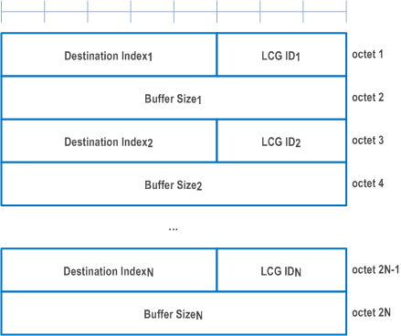
Sidelink Buffer Status Report (SL-BSR) MAC CEs consist of either:
- SL-BSR format (variable size); or
- Truncated SL-BSR format (variable size).
- Destination Index: The Destination Index field identifies the destination. The length of this field is 5 bits. The value is set to one index corresponding to SL destination identity associated to same destination reported in sl-TxResourceReqList, sl-TxResourceReqListDisc, sl-TxResourceReqListCommRelay and sl-TxResourceReqListL2-U2U, if present. The value is indexed sequentially from 0 in the same ascending order of SL destination identity in sl-TxResourceReqList, sl-TxResourceReqListDisc, sl-TxResourceReqListCommRelay and sl-TxResourceReqListL2-U2U as specified in TS 38.331. When multiple lists are reported, the value is indexed sequentially across all the lists in the same order as presented in SidelinkUEInformationNR message;
- LCG ID: The Logical Channel Group ID field identifies the group of logical channel(s) whose SL buffer status is being reported. The length of the field is 3 bits;
- Buffer Size: The Buffer Size field identifies the total amount of data available according to the data volume calculation procedure in TS 38.322 and TS 38.323 across all logical channels of a logical channel group of a destination after the MAC PDU has been built (i.e. after the logical channel prioritization procedure, which may result the value of the Buffer Size field to zero). The amount of data is indicated in number of bytes. The size of the RLC headers and MAC subheaders are not considered in the buffer size computation. The length of this field is 8 bits. The values for the Buffer Size field are shown in Table 6.1.3.1-2, respectively. For the Truncated SL-BSR format the number of Buffer Size fields included is maximised, while not exceeding the number of padding bits.
6.1.3.34 Sidelink Configured Grant Confirmation MAC CE |R16| p. 247
The Sidelink Configured Grant Confirmation MAC CE is identified by a MAC subheader with eLCID as specified in Table 6.2.1-2b. The Sidelink Configured Grant Confirmation MAC CE is defined as follows (Figure 6.1.3.34-1):
- Ci: If there is a configured grant Type 2 with sl-ConfigIndexCG i configured for the MAC entity as specified in TS 38.331, this field indicates the confirmation to activation/deactivation of the configured grant with sl-ConfigIndexCG i, else the MAC entity shall ignore the Ci field. The Ci field is set to 1 to confirm that the configured grant with sl-ConfigIndexCG i shall be activated. The Ci field is set to 0 to indicate that the configured grant with sl-ConfigIndexCG i shall be deactivated.

6.1.3.35 Sidelink CSI Reporting MAC CE |R16| p. 248
The Sidelink CSI Reporting MAC CE is identified by a MAC subheader with LCID as specified in Table 6.2.4-1. The priority of the Sidelink CSI Reporting MAC CE is fixed to '1'. The Sidelink CSI Reporting MAC CE is defined as follows (Figure 6.1.3.35-1):
- RI: This field indicates the derived value of the Rank Indicator for sidelink CSI reporting as specified in clause 8.5 of TS 38.214. The length of the field is 1 bit, the values of the rank indicator field are mapped to allowed rank indicator values with increasing order, where '0' is mapped to the smallest allowed rank indicator value;
- CQI: This field indicates the derived value of the Channel Quality Indicator for sidelink CSI reporting as specified in clause 8.5 of TS 38.214. The length of the field is 4 bit;
- R: Reserved bit, set to 0.

6.1.3.36 SP Positioning SRS Activation/Deactivation MAC CE |R16| p. 248
The SP Positioning SRS Activation/Deactivation MAC CE is identified by a MAC subheader with eLCID as specified in Table 6.2.1-1b. It has a variable size with following fields:
- A/D: This field indicates whether to activate or deactivate indicated SP Positioning SRS resource set. The field is set to 1 to indicate activation, otherwise it indicates deactivation;
- Positioning SRS Resource Set's Cell ID: This field indicates the identity of the Serving Cell, which contains activated/deactivated SP Positioning SRS Resource Set. If the MAC CE is used for activation/deactivation of the SP positioning SRS transmission in RRC_INACTIVE, this field indicates the identity of the cell from where positioning SRS configuration was received. If the C field is set to 0, this field also indicates the identity of the Serving Cell which contains all resources indicated by the Spatial Relation for Resource IDi fields, if present. The length of the field is 5 bits;
- Positioning SRS Resource Set's BWP ID: This field indicates a UL BWP as the codepoint of the DCI bandwidth part indicator field as specified in TS 38.212, which contains activated/deactivated SP Positioning SRS Resource Set. If the C field is set to 0, this field also indicates the identity of the BWP which contains all resources indicated by the Spatial Relation for Resource IDi fields, if present. If the MAC CE is used for activation/deactivation of the SP positioning SRS transmission in RRC_INACTIVE and the SP positioning SRS is configured outside the initial BWP, this field should be ignored by UE. The length of the field is 2 bits;
- C: This field indicates whether the octets containing Resource Serving Cell ID field(s) and Resource BWP ID field(s) within the field Spatial Relation for Resource ID i are present, except for Spatial Relation Resource IDi with DL-PRS or SSB. When A/D is set to 1, if this field is set to 1, the octets containing Resource Serving Cell ID field(s) and Resource BWP ID field(s) in the field Spatial Relation for Resource IDi are present, otherwise if this field is set to 0, they are not present. When A/D is set to 0, this field is always set to 0 that they are not present;
- SUL: This field indicates whether the MAC CE applies to the NUL carrier or SUL carrier configuration. This field is set to 1 to indicate that it applies to the SUL carrier configuration, and it is set to 0 to indicate that it applies to the NUL carrier configuration;
- Positioning SRS Resource Set ID: This field indicates the SP Positioning SRS Resource Set identified by SRS-PosResourceSetId as specified in TS 38.331, which is to be activated or deactivated. The length of the field is 4 bits;
- Spatial Relation for Resource IDi: The field Spatial Relation for Resource IDi is only present if MAC CE is used for activation, i.e. the A/D field is set to 1. M is the total number of Positioning SRS resource(s) configured under the SP Positioning SRS resource set indicated by the field Positioning SRS Resource Set ID. There are 4 types of Spatial Relation for Resource IDi, which is indicated by the F (F0 and F1) field within. The fields within Spatial Relation for Resource IDi are shown in Figure 6.1.3.36-2 to Figure 6.1.3.36-5 for the 4 types of Spatial Relations for Resource IDi;
- S: This field indicates whether the fields Spatial Relation for Resource IDi for the positioning SRS resource i within the positioning SRS resource set are present. If the field is set to 1, the fields Spatial Relation for Resource IDi are present; otherwise, they are absent;
- R: Reserved bit, set to 0.
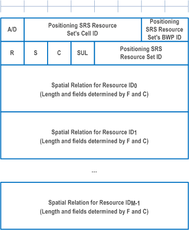
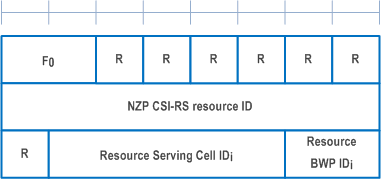
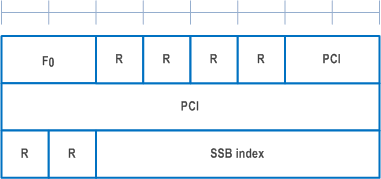
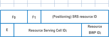
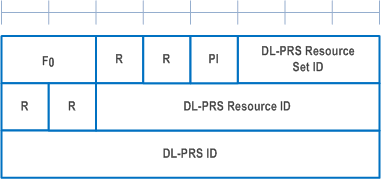
The field Spatial Relation for Resource IDi consists of the following fields:
- F0: This field indicates the type of a resource used as a spatial relation for the ith Positioning SRS resource within the Positioning SRS Resource Set indicated with the field Positioning SRS Resource Set ID. The field is set to 00 to indicate NZP CSI-RS resource index is used; it is set to 01 to indicate SSB index is used; it is set to 10 to indicate SRS resource index is used; it is set to 11 to indicate DL-PRS index is used. The length of the field is 2 bits;
- F1: This field indicates the type of SRS resource used as spatial relation for the ith Positioning SRS resource within the SP Positioning SRS Resource Set indicated with the field Positioning SRS Resource Set ID when F0 is set to 10. The field is set to 0 to indicate SRS resource index SRS-ResourceId as defined in TS 38.331 is used; the field is set to 1 to indicate Positioning SRS resource index SRS-PosResourceId as defined in TS 38.331 is used;
- NZP CSI-RS Resource ID: This field contains an index of NZP-CSI-RS-ResourceID, as specified in TS 38.331, indicating the NZP CSI-RS resource, which is used to derive the spatial relation for the positioning SRS. The length of the field is 8 bits;
- SSB index: This field contains an index of SSB SSB-Index as specified in TS 38.331 and/or TS 37.355. The length of the field is 6 bits;
- PCI: This field contains physical cell identity PhysCellId as specified in TS 38.331 and/or TS 37.355. The length of the field is 10 bits;
- SRS resource ID: When F1 is set to 0, the field indicates an index for SRS resource SRS-ResourceId as defined in TS 38.331; When F1 is set to 1, the field indicates an index for Positioning SRS resource SRS-PosResourceId as defined in TS 38.331. The length of the field is 5 bits representing the index from 0 to 31;
- E: This field indicates the extension of SRS resource ID as the MSB of SRS resource ID. The total length of the extended SRS resource ID is 6 bits. If E bit is set to 1, the SRS resource ID value is 5-bit SRS resource ID field + 32;
- DL-PRS Resource Set ID: This field contains an index for DL-PRS Resource Set nr-DL-PRS-ResourceSetId as defined in TS 37.355. The length of the field is 3 bits;
- DL-PRS Resource ID: This field contains an index for DL-PRS resource nr-DL-PRS-Resource-Id as defined in TS 37.355. The length of the field is 6 bits;
- DL-PRS ID: This field contains an identity for DL-PRS resource dl-PRS-ID as defined in TS 37.355. The length of the field is 8 bits;
- PI: This field indicates whether the field DL-PRS resource ID is present within the Spatial Relation for Resource IDi with DL-PRS. If the field is set to 1, the octet containing the field DL-PRS resource ID is present; otherwise, the octet is omitted;
- SI: This field indicates whether the field SSB index is present within the Spatial Relation for Resource IDi with SSB. If the field is set to 1, the octet containing the field SSB index is present; otherwise, the octet is omitted;
- Resource Serving Cell IDi: This field indicates the identity of the Serving Cell on which the resource used for spatial relationship derivation for the ith Positioning SRS resource is located. The length of the field is 5 bits;
- Resource BWP IDi: This field indicates a UL BWP as the codepoint of the DCI bandwidth part indicator field as specified in TS 38.212, on which the resource used for spatial relationship derivation for the ith Positioning SRS resource is located. The length of the field is 2 bits.