Content for TS 38.401 Word version: 18.4.0
1…
5…
6…
6.1.4
6.1.5…
6.2…
7…
8…
8.2…
8.2.1.4…
8.2.2…
8.2.3…
8.2.4
8.2.5
8.3…
8.4…
8.4.4…
8.5…
8.9…
8.9.4…
8.9.6…
8.9.7…
8.10
8.11…
8.12…
8.13…
8.14…
8.15…
8.15.2…
8.16…
8.17…
8.17.3…
8.17.4
8.18…
8.19…
8.19.2
8.19.3
8.19.4…
8.21…
8.22…
8.23…
8.24…
9…
A…
A Deployment scenarios of gNB/en-gNB
B NG-RAN Architecture for Radio Access Network Sharing with multiple cell ID broadcast (informative)
$ Change History
A Deployment scenarios of gNB/en-gNB p. 157
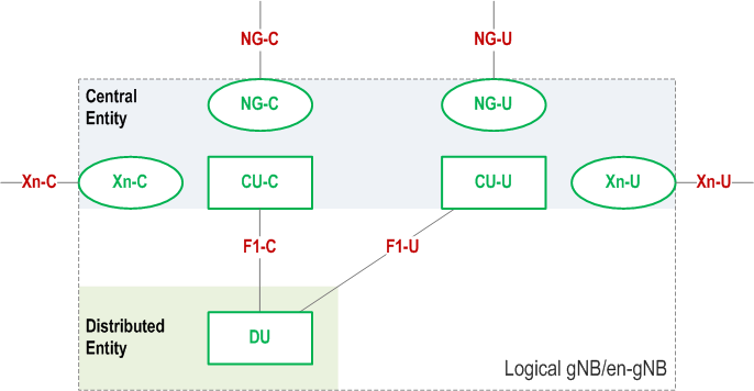
Figure A-1 shows logical nodes (CU-C, CU-U and DU), internal to a logical gNB/en-gNB. Protocol terminations of the NG and Xn interfaces are depicted as ellipses in Figure A-1. The terms "Central Entity" and "Distributed Entity" shown in Figure A-1 refer to physical network nodes.

B NG-RAN Architecture for Radio Access Network Sharing with multiple cell ID broadcast (informative) p. 158
Each gNB-DU serving a cell identified by a Cell Identity associated with a subset of PLMNs is connected to a gNB-CU via a single F1-C interface instance.
Each F1-C interface instance is setup individually.
F1-C interface instances terminating at gNB-DUs which share the same physical radio resources may share the same F1-C signalling transport resources. If this option is applied,
- non-UE associated signalling is associated to an F1-C interface instance by allocating the corresponding Transaction ID from a value range associated to that F1-C interface instance.
- node related, non-UE associated F1-C interface signalling may provide information destined for multiple logical nodes in a single F1AP procedure instance once the F1-C interface instance is setup.
- a UE associated signalling connection is associated to an F1-C interface instance by allocating values for the corresponding gNB-DU UE F1AP ID and gNB-CU UE F1AP ID so that they can be mapped to that interface instance.