Content for TS 38.401 Word version: 18.4.0
1…
5…
6…
6.1.4
6.1.5…
6.2…
7…
8…
8.2…
8.2.1.4…
8.2.2…
8.2.3…
8.2.4
8.2.5
8.3…
8.4…
8.4.4…
8.5…
8.9…
8.9.4…
8.9.6…
8.9.7…
8.10
8.11…
8.12…
8.13…
8.14…
8.15…
8.15.2…
8.16…
8.17…
8.17.3…
8.17.4
8.18…
8.19…
8.19.2
8.19.3
8.19.4…
8.21…
8.22…
8.23…
8.24…
9…
A…
6 NG-RAN architecture
6.1 Overview
6.1.1 Overall Architecture of NG-RAN
6.1.2 Overall architecture for separation of gNB-CU-CP and gNB-CU-UP
6.1.3 Overall Architecture of IAB
...
...
6 NG-RAN architecture p. 15
6.1 Overview p. 15
6.1.1 Overall Architecture of NG-RAN p. 15

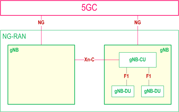
The NG-RAN consists of a set of gNBs connected to the 5GC through the NG interface.
An gNB can support FDD mode, TDD mode or dual mode operation.
gNBs can be interconnected through the Xn interface.
A gNB may consist of a gNB-CU and one or more gNB-DU(s). A gNB-CU and a gNB-DU is connected via F1 interface.
One gNB-DU is connected to only one gNB-CU.
NG, Xn and F1 are logical interfaces.
For NG-RAN, the NG and Xn-C interfaces for a gNB consisting of a gNB-CU and gNB-DUs, terminate in the gNB-CU. For EN-DC, the S1-U and X2-C interfaces for a gNB consisting of a gNB-CU and gNB-DUs, terminate in the gNB-CU. The gNB-CU and connected gNB-DUs are only visible to other gNBs and the 5GC as a gNB. A possible deployment scenario is described in Annex A.
The node hosting user plane part of NR PDCP (e.g. gNB-CU, gNB-CU-UP, and for EN-DC, MeNB or SgNB depending on the bearer split) shall perform user inactivity monitoring and further informs its inactivity or (re)activation to the node having C-plane connection towards the core network (e.g. over E1, X2). The node hosting NR RLC (e.g. gNB-DU) may perform user inactivity monitoring and further inform its inactivity or (re)activation to the node hosting control plane, e.g. gNB-CU or gNB-CU-CP.
UL PDCP configuration (i.e. how the UE uses the UL at the assisting node) is indicated via X2-C (for EN-DC), Xn-C (for NG-RAN) and F1-C. Radio Link Outage/Resume for DL and/or UL is indicated via X2-U (for EN-DC), Xn-U (for NG-RAN) and F1-U.
The NG-RAN is layered into a Radio Network Layer (RNL) and a Transport Network Layer (TNL).
The NG-RAN architecture, i.e. the NG-RAN logical nodes and interfaces between them, is defined as part of the RNL.
For each NG-RAN interface (NG, Xn, F1) the related TNL protocol and the functionality are specified. The TNL provides services for user plane transport, signalling transport.
In NG-Flex configuration, each NG-RAN node is connected to all AMFs of AMF Sets within an AMF Region supporting at least one slice also supported by the NG-RAN node. The AMF Set and the AMF Region are defined in TS 23.501.
If security protection for control plane and user plane data on TNL of NG-RAN interfaces has to be supported, NDS/IP TS 33.501 shall be applied.
6.1.2 Overall architecture for separation of gNB-CU-CP and gNB-CU-UP p. 16
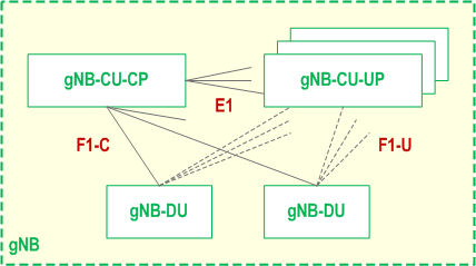
The overall architecture for separation of gNB-CU-CP and gNB-CU-UP is depicted in Figure 6.1.2-1.

- A gNB may consist of a gNB-CU-CP, multiple gNB-CU-UPs and multiple gNB-DUs;
- The gNB-CU-CP is connected to the gNB-DU through the F1-C interface;
- The gNB-CU-UP is connected to the gNB-DU through the F1-U interface;
- The gNB-CU-UP is connected to the gNB-CU-CP through the E1 interface;
- One gNB-DU is connected to only one gNB-CU-CP;
- One gNB-CU-UP is connected to only one gNB-CU-CP;
- One gNB-DU can be connected to multiple gNB-CU-UPs under the control of the same gNB-CU-CP;
- One gNB-CU-UP can be connected to multiple DUs under the control of the same gNB-CU-CP;
6.1.3 Overall Architecture of IAB |R16| p. 17

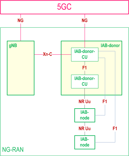
The NG-RAN supports IAB by the IAB-node wirelessly connecting to the gNB capable of serving the IAB-nodes, named IAB-donor.
The IAB-donor consists of an IAB-donor-CU and one or more IAB-donor-DU(s). In case of separation of gNB-CU-CP and gNB-CU-UP, the IAB-donor may consist of an IAB-donor-CU-CP, multiple IAB-donor-CU-UPs and multiple IAB-donor-DUs.
The IAB-node connects to an upstream IAB-node or an IAB-donor-DU via a subset of the UE functionalities of the NR Uu interface (named IAB-MT function of IAB-node). The IAB-node provides wireless backhaul to the downstream IAB-nodes and UEs via the network functionalities of the NR Uu interface (named IAB-DU function of IAB-node).
The F1-C traffic between an IAB-node and IAB-donor-CU is backhauled via the IAB-donor-DU and the optional intermediate hop IAB-node(s).
The F1-U traffic between an IAB-node and IAB-donor-CU is backhauled via the IAB-donor-DU and the optional intermediate hop IAB-node(s).
All functions specified for a gNB-DU are equally applicable for an IAB-DU and IAB-donor-DU, unless otherwise stated, and all functions specified for a gNB-CU are equally applicable for an IAB-donor-CU, unless otherwise stated. All functions specified for the UE context are equally applicable for managing the context of IAB-MT, unless otherwise stated.