Content for TS 38.401 Word version: 18.4.0
1…
5…
6…
6.1.4
6.1.5…
6.2…
7…
8…
8.2…
8.2.1.4…
8.2.2…
8.2.3…
8.2.4
8.2.5
8.3…
8.4…
8.4.4…
8.5…
8.9…
8.9.4…
8.9.6…
8.9.7…
8.10
8.11…
8.12…
8.13…
8.14…
8.15…
8.15.2…
8.16…
8.17…
8.17.3…
8.17.4
8.18…
8.19…
8.19.2
8.19.3
8.19.4…
8.21…
8.22…
8.23…
8.24…
9…
A…
8 Overall procedures in gNB-CU/gNB-DU Architecture p. 30
8.1 UE Initial Access p. 30
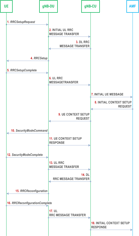
The signalling flow for UE Initial access is shown in Figure 8.1-1.

Step 1.
The UE sends an RRCSetupRequest message to the gNB-DU.
Step 2.
The gNB-DU includes the RRC message and, if the UE is admitted, the corresponding low layer configuration for the UE in the INITIAL UL RRC MESSAGE TRANSFER message and transfers to the gNB-CU. The INITIAL UL RRC MESSAGE TRANSFER message includes the C-RNTI allocated by the gNB-DU. If the gNB-DU identifies the UE as a Reduced Capability UE during the random access procedure, a NR RedCap UE Indication is provided in the INITIAL UL RRC MESSAGE TRANSFER message.
Step 3.
The gNB-CU allocates a gNB-CU UE F1AP ID for the UE and generates a RRCSetup message towards UE. The RRC message is encapsulated in -the DL RRC MESSAGE TRANSFER message.
Step 4.
The gNB-DU sends the RRCSetup message to the UE.
Step 5.
The UE sends the RRC CONNECTION SETUP COMPLETE message to the gNB-DU.
Step 6.
The gNB-DU encapsulates the RRC message in the UL RRC MESSAGE TRANSFER message and sends it to the gNB-CU.
Step 7.
The gNB-CU sends the INITIAL UE MESSAGE message to the AMF.
Step 8.
The AMF sends the INITIAL CONTEXT SETUP REQUEST message to the gNB-CU.
Step 9.
The gNB-CU sends the UE CONTEXT SETUP REQUEST message to establish the UE context in the gNB-DU. In this message, it may also encapsulate the SecurityModeCommand message. In case of NG-RAN sharing, the gNB-CU includes the serving PLMN ID (for SNPNs the serving SNPN ID).
Step 10.
The gNB-DU sends the SecurityModeCommand message to the UE.
Step 11.
The gNB-DU sends the UE CONTEXT SETUP RESPONSE message to the gNB-CU.
Step 12.
The UE responds with the SecurityModeComplete message.
Step 13.
The gNB-DU encapsulates the RRC message in the UL RRC MESSAGE TRANSFER message and sends it to the gNB-CU.
Step 14.
The gNB-CU generates the RRCReconfiguration message and encapsulates it in the DL RRC MESSAGE TRANSFER message.
Step 15.
The gNB-DU sends RRCReconfiguration message to the UE.
Step 16.
The UE sends RRCReconfigurationComplete message to the gNB-DU.
Step 17.
The gNB-DU encapsulates the RRC message in the UL RRC MESSAGE TRANSFER message and send it to the gNB-CU.
Step 18.
The gNB-CU sends the INITIAL CONTEXT SETUP RESPONSE message to the AMF.