Content for TS 38.401 Word version: 18.4.0
1…
5…
6…
6.1.4
6.1.5…
6.2…
7…
8…
8.2…
8.2.1.4…
8.2.2…
8.2.3…
8.2.4
8.2.5
8.3…
8.4…
8.4.4…
8.5…
8.9…
8.9.4…
8.9.6…
8.9.7…
8.10
8.11…
8.12…
8.13…
8.14…
8.15…
8.15.2…
8.16…
8.17…
8.17.3…
8.17.4
8.18…
8.19…
8.19.2
8.19.3
8.19.4…
8.21…
8.22…
8.23…
8.24…
9…
A…
8.13 Overall procedures for MDT
8.13.0 General
8.13.1 Signalling based MDT activation
8.13.2 Management based MDT activation
8.13.2.1 General
8.13.2.2 Management based MDT Activation in gNB-CU-CP
8.13.2.3 Management based MDT Activation in gNB-DU
8.13.2.4 Management based MDT Activation in gNB-CU-UP
8.13.2.5 User consent propagation in EN-DC
8.13.2.6 User consent propagation in MR-DC with 5GC
8.13.2.7 Management based trace activation in MR-DC with 5GC
8.13.3 Alignment of MDT and QoE Measurements
8.13.4 MDT reporting
...
...
8.13 Overall procedures for MDT |R16| p. 93
8.13.0 General |R17| p. 93
The following clauses describe the overall procedures for MDT (TS 37.320) involving E1 and F1.
8.13.1 Signalling based MDT activation p. 93
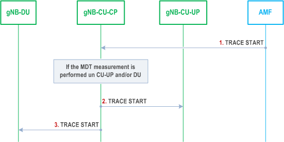
The signalling flow for Signalling based MDT activation triggered by AMF involving E1 and F1 is shown in Figure 8.13.1-1.
Step 1.
The AMF sends a TRACE START message to the gNB. The AMF considers MDT user consent information for the UE as defined in TS 32.422. TRACE START message includes the parameters for configuring MDT measurements.
Step 2.
The gNB-CU-CP decides if the gNB-CU-UP, or the gNB-DU, or both, should be involved in the MDT measurement. If the gNB-CU-UP should be involved in the MDT measurement, the gNB-CU-CP sends TRACE START message to the gNB-CU-UP, including MDT configuration parameters.
Step 3.
If the gNB-DU should be involved in the MDT measurement, the gNB-CU-CP sends TRACE START message to the gNB-DU, including MDT configuration parameters.
8.13.2 Management based MDT activation p. 94
8.13.2.1 General p. 94
In Management Based Trace Activation towards a gNB-CU-CP, gNB-CU-UP or a gNB-DU can be fulfilled with the Cell Traffic trace functionality defined in TS 32.422. The configuration parameters of the Trace Session that are received by a node in split RAN architecture are defined in TS 32.422.
The following description is valid for both an en-gNB and a gNB.
If the MDT measurement is initiated by the EM towards the gNB-CU-CP, and if the activation involves measurements collected by multiple nodes under the same gNB-CU-CP control in a split RAN architecture, the EM sends MDT measurement activation to the gNB-CU-CP and the gNB-CU-CP may further decide which gNB-DU(s) or which gNB-CU-UP(s) to perform the MDT measurement.
When gNB-CU-CP or a gNB-DU receive the Trace Session Activation message from the management system for a given cell or a list of cell(s) under its control, the gNB-CU-CP or gNB-DU shall start a Trace Session for the given cell or list of cell(s). For Management Based MDT sent directly to a gNB-CU-UP, no MDT Area Configuration (apart from PLMN IDs) is to be included in the MDT activation indication.
The signalling flows for management based MDT activation in gNB-CU-CP, gNB-DU and gNB-CU-UP are shown in Figure 8.13.2.2-1, Figure 8.13.2.3-1 and in Figure 8.13.2.4-1 respectively.
8.13.2.2 Management based MDT Activation in gNB-CU-CP p. 94
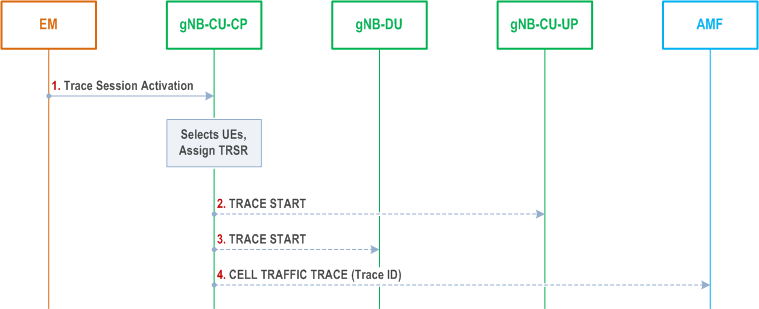
The signalling flow for Management based MDT Activation in gNB-CU-CP is shown in Figure 8.13.2.2-1.
Step 1.
If the UE reports an indication of measurement pollution, the gNB-CU-CP shall, if supported, include such indication as part of the measurement report to be sent to the TCE so that the TCE is able to correlate and filter the affected measurements.
The EM sends a Trace Session activation request to the gNB-CU-CP. This request includes the parameters for configuring UE measurements.
Step 2.
The gNB-CU-CP shall check the MDT user consent requirements configured by OAM and select the suitable UEs for MDT data collection as defined in TS 32.422. In particular, if the MDT configuration contains both MDT measurements subject to user consent and not subject to user consent, the gNB-CU-CP shall if supported:
Step 3.
- If the MDT subscriber provided consent, start a Trace Session and configure with all the MDT measurements in the Trace Session.
- If the MDT subscriber did not provide consent, start a Trace Session and configure with the MDT measurements not subject to user consent in the Trace Session.
For each selected UE, if the gNB-DU should perform MDT measurement, the gNB-CU-CP sends TRACE START message to the gNB-DU, including MDT configuration parameters.
Step 4.
The gNB-CU-CP may send CELL TRAFFIC TRACE message to the AMF for the selected UE, including Trace ID for MDT. The AMF forwards Trace ID and other information to the TCE as specified in TS 32.422.
8.13.2.3 Management based MDT Activation in gNB-DU p. 95
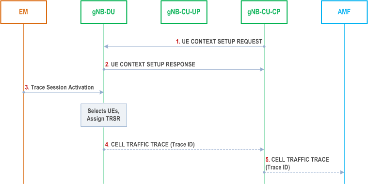
The signalling flow for Management based MDT Activation in gNB-DU is shown in Figure 8.13.2.3-1.
Step 1.
The gNB-CU-CP sends UE CONTEXT SETUP REQUEST message to the gNB-DU, including Management based MDT PLMN List. The message may include the Polluted Measurement Indicator IE. If the gNB-DU has received the Polluted Measurement Indicator IE, the gNB-DU includes the information contained in such indicator as part of the measurement report to be sent to the TCE, so that the TCE is able to correlate and filter the affected measurements.
Step 2.
The gNB-DU sends UE CONTEXT SETUP RESPONSE message to the gNB-CU-CP.
Step 3.
The EM sends a Trace Session activation request to the gNB-DU. This request includes the parameters for configuring UE measurements.
Step 4.
The gNB-DU shall check the MDT user consent requirements configured by OAM and select the suitable UEs for MDT data collection as defined in TS 32.422. In particular, if the MDT configuration contains both MDT measurements subject to user consent and not subject to user consent, the gNB-DU shall if supported:
Step 5.
- If the MDT subscriber provided consent, start a Trace Session and configure with all the MDT measurements in the Trace Session.
- If the MDT subscriber did not provide consent, start a Trace Session and configure with the MDT measurements not subject to user consent in the Trace Session.
Upon reception of a CELL TRAFFIC TRACE message from F1, the gNB-CU-CP shall send CELL TRAFFIC TRACE message to the AMF for this UE, including Trace ID for MDT. The AMF forwards Trace ID and other information to the TCE as specified in TS 32.422.
8.13.2.4 Management based MDT Activation in gNB-CU-UP p. 96
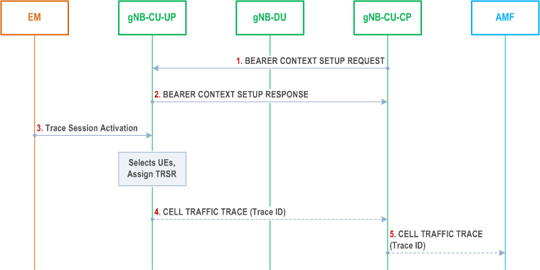
The signalling flow for Management based MDT Activation in gNB-CU-UP is shown in Figure 8.13.2.4-1.
Step 1.
The gNB-CU-CP sends BEARER CONTEXT SETUP REQUEST message to the gNB-CU-UP, including Management based MDT PLMN List. The message may include Polluted Measurement Indicator. If the gNB-DU has received the Polluted Measurement Indicator IE, the gNB-DU includes the information contained in such indicator as part of the measurement report to be sent to the TCE so that the TCE is able to correlate and filter the affected measurements.
Step 2.
The gNB-CU-UP sends BEARER CONTEXT SETUP RESPONSE message to the gNB-CU-CP.
Step 3.
The EM sends a Trace Session activation request to the gNB-CU-UP. This request includes the parameters for configuring UE measurements.
Step 4.
The gNB-CU-UP shall check the MDT user consent requirements configured by OAM and select the suitable UEs for MDT data collection as defined in TS 32.422. In particular, if the MDT configuration contains both MDT measurements subject to user consent and not subject to user consent, the gNB-CU-UP shall if supported:
Step 5.
- If the MDT subscriber provided consent, start a Trace Session and configure with all the MDT measurements in the Trace Session.
- If the MDT subscriber did not provide consent, start a Trace Session and configure with the MDT measurements not subject to user consent in the Trace Session.
Upon reception of a CELL TRAFFIC TRACE message from E1, the gNB-CU-CP shall send CELL TRAFFIC TRACE message to the AMF for this UE, including Trace ID for MDT. The AMF forwards Trace ID and other information to the TCE as specified in TS 32.422.
8.13.2.5 User consent propagation in EN-DC p. 97
In the EN-DC case, the EM provides the MDT configuration to both MeNB and en-gNB independently.
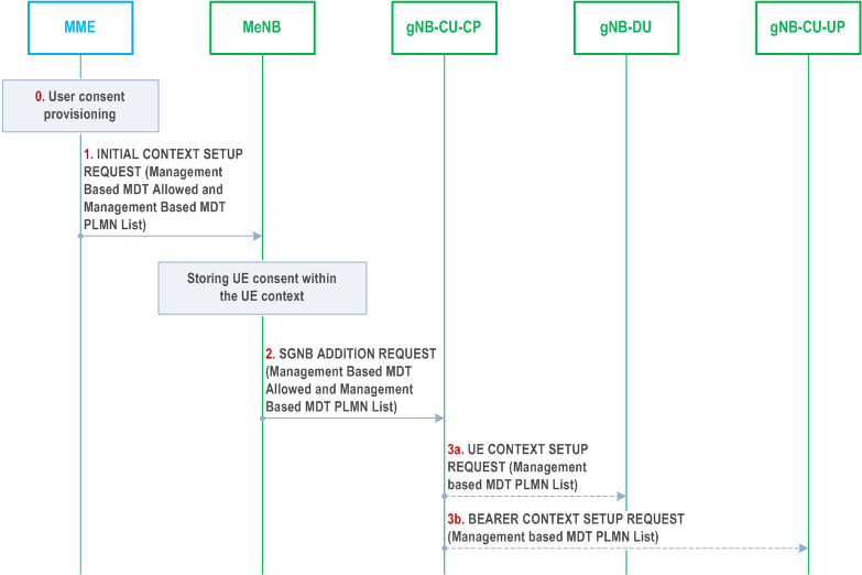
As specified in TS 32.422 in Management based MDT getting user consent is required before activating the MDT functionality because of privacy and legal obligations. In the case of EN-DC user consent gets communicated to the MeNB at the UE context setup procedure using the INITIAL CONTEXT SETUP REQUEST message. In particular when the Management Based MDT Allowed IE is contained in the INITIAL CONTEXT SETUP REQUEST message, the MeNB stores it in the UE context and uses it, together with information in the Management Based MDT PLMN List IE, if available, to allow subsequent selection of the UE for management based MDT as specified in TS 32.422. The MeNB may also receive user consent information in the HANDOVER REQUEST message. The MeNB will forward the MDT user consent to the SgNB at EN-DC setup. In particular, if available in the UE context, the MeNB will include the Management Based MDT Allowed IE and the Management Based MDT PLMN List IE in the SGNB ADDITION REQUEST message to the SgNB. Furthermore, the user consent will be forwarded to the relevant gNB-CU-UP at the bearer context setup or to the gNB-DU by including the Management Based MDT PLMN List IE in the BEARER CONTEXT SETUP REQUEST or UE CONTEXT SETUP REQUEST.
The signalling flow for User consent proposation in EN-DC is shown in Figure 8.13.2.5-1.
Step 0.
User Context information are made available at the MME.
Step 1.
The MME sends INITIAL CONTEXT SETUP REQUEST message to the MeNB, including Management Based MDT Allowed IE and the Management based MDT PLMN List IE to communicate user consent to the eNB.
Step 2.
The MeNB sends SGNB ADDITION REQUEST to the gNB-CU-CP at EN-DC setup. This request includes Management Based MDT Allowed IE and, optionally, the Management based MDT PLMN List IE, if available.
Step 3a.
The user consent is communicated to the gNB-DU at the UE context setup by including the Management based MDT PLMN List IE in the UE CONTEXT SETUP REQUEST.
Step 3b.
The user consent is communicated to the gNB-CU-UP at the bearer context setup by including the Management based MDT PLMN List IE in the BEARER CONTEXT SETUP REQUEST.
8.13.2.6 User consent propagation in MR-DC with 5GC |R17| p. 98
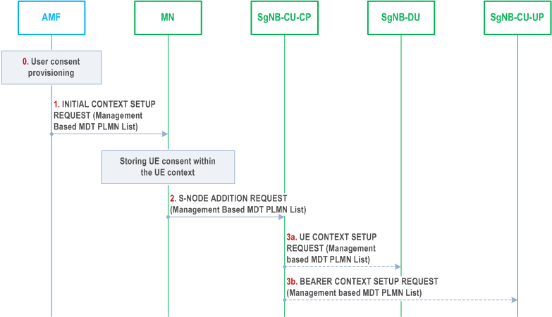
As specified in TS 32.422 in Management based MDT getting user consent is required before activating the MDT functionality because of privacy and legal obligations. User consent is communicated to the MN at the UE context setup procedure using the INITIAL CONTEXT SETUP REQUEST message, or in HANDOVER REQUEST and PATH SWITCH REQUEST ACKNOWLEDGE messages. Modified user consent information may be received in the UE CONTEXT MODIFICATION REQUEST message. The MN stores the received information in the UE context and uses it to allow subsequent selection of the UE for management based MDT as specified in TS 32.422. The MN will forward the MDT user consent to the SN at MR-DC setup, i.e., if available in the UE context, the MN will include the Management Based MDT PLMN List IE in the S-NODE ADDITION REQUEST message or in the S-NODE MODIFICATION REQUEST message sent to the SN. Furthermore, in NR-DC and NGEN-DC, the user consent will be forwarded to the relevant SgNB-CU-UP at the bearer context setup or to the SgNB-DU by including the Management Based MDT PLMN List information in the BEARER CONTEXT SETUP REQUEST or UE CONTEXT SETUP REQUEST. Furthermore, in NR-DC and NGEN-DC, the user consent may be updated to the relevant SgNB-CU-UP at the bearer context modification or to the SgNB-DU by including the Management Based MDT PLMN List information in the BEARER CONTEXT MODIFICATION REQUEST or UE CONTEXT MODIFICATION REQUEST.
The signalling flow for User consent propagation in NR-DC and NGEN-DC is shown in Figure 8.13.2.6-1.
Step 0.
User Context information are made available at the AMF.
Step 1.
The AMF sends INITIAL CONTEXT SETUP REQUEST message to the MN, including the Management based MDT PLMN List IE to communicate user consent to the MN.
Step 2.
The MN sends S-NODE ADDITION REQUEST to the SgNB-CU-CP at NR-DC setup. This request includes the Management based MDT PLMN List IE.
Step 3a.
The user consent is communicated to the SgNB-DU at the UE context setup by including the Management based MDT PLMN List IE in the UE CONTEXT SETUP REQUEST.
Step 3b.
The user consent is communicated to the SgNB-CU-UP at the bearer context setup by including the Management based MDT PLMN List IE in the BEARER CONTEXT SETUP REQUEST.
8.13.2.7 Management based trace activation in MR-DC with 5GC |R17| p. 99
In the MR-DC with 5GC case, the EM provides the MDT configuration to both MN and SN independently.
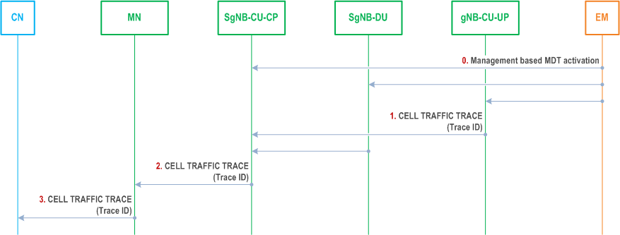
In Management Based Trace Activation towards a SN, the SN may send the CELL TRAFFIC TRACE message including the Trace ID and privacy indicator to the MN as described in TS 32.422. Upon reception of the CELL TRAFFIC TRACE message from the SN, the MN will send a CELL TRAFFIC TRACE message including the Trace ID and privacy indicator to the CN for this UE. The CN forwards the Trace ID and other information to the TCE as specified in TS 32.422.
The following shows a flow chart summarizing the functionality in MR-DC when the SN is the SgNB.
Step 0.
The gNB-CU-CP, the gNB-CU-UP, the gNB-DU receives the MDT configuration from EM and select the suitable UEs for MDT data collection. The anonymization MDT configuration parameter from the EM is considered to be IMEI-TAC.
Step 1.
For the management based MDT activation in gNB-CU-UP and/or in gNB-DU, if the gNB-CU-UP and/or the gNB-DU receive an MDT Configuration including the anonymization parameter set to IMEI-TAC, the gNB-CU-UP and/or gNB-DU send CELL TRAFFIC TRACE message to the gNB-CU-CP for this UE, including Trace ID and privacy indicator.
Step 2.
For the management based MDT activation in gNB-CU-CP, upon receiving the CELL TRAFFIC TRACE message from E1/F1, the gNB-CU-CP shall send a CELL TRAFFIC TRACE message to the MN for this UE, including Trace ID and privacy indicator.
Step 3.
The MN sends a CELL TRAFFIC TRACE message to the CN for this UE, including Trace ID and privacy indicator. The CN forwards Trace ID and other information to the TCE as specified in TS 32.422.
8.13.3 Alignment of MDT and QoE Measurements |R17| p. 100
In case of split gNB architecture, the gNB-CU-CP can send the TRACE START message for the MDT measurement subject to alignment with a QoE measurement to the gNB-CU-UP and gNB-DU, e.g., upon/after the reception of QoE measurement session start indication from the UE, as specified in TS 38.300.
8.13.4 MDT reporting |R17| p. 100
Each node involved in the MDT measurement reports the measurements collected directly to the TCE the node has been configured with.
In the case where issues (e.g. in-device coexistence problem) potentially affecting immediate MDT measurements were detected during a measurement reporting process, an indication of the issue should be logged in the affected measurement reports to the TCE so that the TCE is able to correlate and filter the affected measurements.