Content for TS 38.401 Word version: 18.4.0
1…
5…
6…
6.1.4
6.1.5…
6.2…
7…
8…
8.2…
8.2.1.4…
8.2.2…
8.2.3…
8.2.4
8.2.5
8.3…
8.4…
8.4.4…
8.5…
8.9…
8.9.4…
8.9.6…
8.9.7…
8.10
8.11…
8.12…
8.13…
8.14…
8.15…
8.15.2…
8.16…
8.17…
8.17.3…
8.17.4
8.18…
8.19…
8.19.2
8.19.3
8.19.4…
8.21…
8.22…
8.23…
8.24…
9…
A…
8.23 Mobile IAB migration procedures
8.23.1 Migration of mobile IAB-MT via Xn handover
8.23.2 Migration of mobile IAB-MT via NG handover
8.23.3 Mobile IAB-DU migration procedure
8.23.4 Mobile IAB-node RLF recovery
...
...
8.23 Mobile IAB migration procedures |R18| p. 147
8.23.1 Migration of mobile IAB-MT via Xn handover p. 147
The mobile IAB-MT can be migrated from a source RRC-terminating IAB-donor-CU to a target RRC-terminating IAB-donor-CU using the Xn handover procedure. During this migration, the mobile IAB-DU co-located with the mobile IAB-MT is connected to an F1-terminating IAB-donor-CU, which may be the same as the source RRC-terminating IAB-donor-CU or the target RRC-terminating IAB-donor-CU, or it can be different from both the source and the target RRC-terminating IAB-donor-CU.
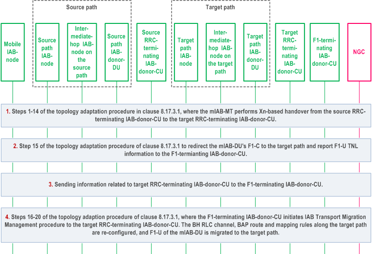
Figure 8.23.1-1 shows an example of mobile IAB-MT migration via Xn handover for the case when the F1-terminating IAB-donor-CU is different from the source RRC-terminating IAB-donor-CU and the target RRC-terminating IAB-donor-CU. In this example, the mobile IAB-MT is connected to the source RRC-terminating IAB-donor-CU via a source path of an IAB topology before the migration, and it is connected to the target RRC-terminating IAB-donor-CU via a target path of a different IAB topology after the migration.

Step 1.
Steps 1-14 of the topology adaptation procedure in clause 8.17.3.1 are performed to conduct Xn handover of the mobile IAB-MT from the source parent IAB-node connected to the source RRC-terminating IAB-donor-CU to the target parent IAB-node connected to the target RRC-terminating IAB-donor-CU. In these steps, the mobile IAB-node corresponds to the migrating IAB-node in clause 8.17.3.1, and the mobile IAB-MT's source and target RRC-terminating IAB-donor-CUs correspond to the respective source and target IAB-donor-CUs of clause 8.17.3.1. The source RRC-terminating IAB-donor-CU should retain the UE XnAP IDs allocated for the mobile IAB-MT as long as the mobile IAB-MT is connected.
Step 2.
Same as step 15 of the topology adaptation procedure in clause 8.17.3.1, where the F1-C connection between the co-located mobile IAB-DU and its F1-terminating IAB-donor-CU is switched, by using the gNB-DU Configuration Update procedure, to the target path using the new TNL address information of the IAB-MT. In this step, the mobile IAB-node corresponds to the migrating IAB-node, and the F1-terminating IAB-donor-CU corresponds to the source IAB-donor-CU.
Step 3.
The mobile IAB-DU passes to the F1-terminating IAB-donor-CU the gNB ID of the target RRC-terminating IAB-donor-CU and the mobile IAB-node's BAP address allocated by the target RRC-terminating IAB-donor-CU via a GNB-DU CONFIGURATION UPDATE message. In case the migration of the mobile IAB-MT occurs during mobile IAB-DU migration, each logical mobile IAB-DU passes this information to its respective F1-terminating IAB-donor-CU. The F1-terminating IAB-donor-CU retains the UE XnAP ID that it allocated to the mobile IAB-MT as long as the co-located mobile IAB-DU connects to this CU, and retains the UE XnAP ID allocated for the mobile IAB-MT by the source RRC-terminating IAB-donor-CU until the present step (step 3).
Step 4.
Same as steps 16-20 of the topology adaptation procedure in clause 8.17.3.1, where the F1-terminating IAB-donor-CU initiates the IAB Transport Migration Management procedure towards the target RRC-terminating IAB-donor-CU to provide the context of the offloaded traffic. If the IAB Transport Migration Management procedure is the first XnAP procedure for the mobile IAB-MT between the F1-terminating IAB-donor-CU and the target RRC-terminating IAB-donor-CU, the F1-terminating IAB-donor-CU includes the mobile IAB-MT's BAP address in the IAB TRANSPORT MIGRATION MANAGEMENT REQUEST message towards the target RRC-terminating IAB-donor-CU. The target RRC-terminating IAB-donor-CU reconfigures the BAP sublayer and/or BH RLC channels on the target path accordingly, and provides the UL BH information for UL BH reconfigurations to be conducted by the F1-terminating IAB-donor-CU on the mobile IAB-node. Then, the F1-U connections of the mobile IAB-node are migrated to the target path.
8.23.2 Migration of mobile IAB-MT via NG handover p. 148
The mobile IAB-MT can be migrated from a source RRC-terminating IAB-donor-CU to a target RRC-terminating IAB-donor-CU using the NG handover procedure. During this migration, the mobile IAB-DU co-located with the mobile IAB-MT is connected to an F1-terminating IAB-donor-CU, which may be the same as the source RRC-terminating IAB-donor-CU or the target RRC-terminating IAB-donor-CU, or it can be different from both the source and the target RRC-terminating IAB-donor-CU.
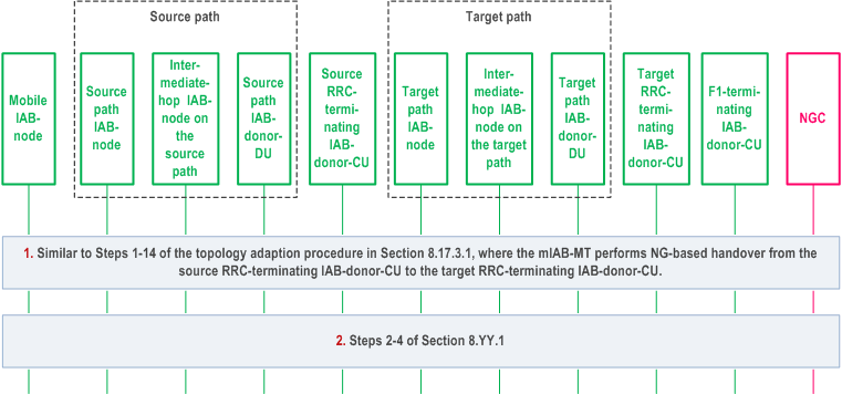
Figure 8.23.2-1 shows an example of mobile IAB-MT migration via NG handover. In this example, the mobile IAB-MT is connected to the source RRC-terminating IAB-donor-CU via a source path of an IAB topology before the migration, and it is connected to the target RRC-terminating IAB-donor-CU via a target path of a different IAB topology after the migration.

Step 1.
Similar to Step 1-14 in clause 8.17.3.1, where the NG-based handover procedure as defined in clauses 4.9.1.3.2 and 4.9.1.3.3 in TS 23.502 is used instead of Xn-based handover procedure.
Step 2.
Same as step 2 to step 4 in clause 8.23.1.
8.23.3 Mobile IAB-DU migration procedure p. 149
To support the mobile IAB-DU migration procedure, the mobile IAB-node concurrently supports two logical mobile IAB-DUs, which have F1 connections set up with the source F1-terminating IAB-donor-CU and target F1-terminating IAB-donor-CU, respectively. The mobile IAB-MT's IAB-donor-CU may be same as either the source F1-termainting IAB-donor CU or the target F1-terminating IAB-donor-CU, or it may be different from both source and target F1-terminating IAB-donor-CUs.
The UE(s) connected to the mobile IAB-node are handed over from the cell(s) of the source logical mobile IAB-DU that have F1 set up with the source F1-terminating IAB-donor-CU to the cell(s) of the target logical mobile IAB-DU that have F1 set up with the target F1-terminating IAB-donor-CU. After the UE(s) are handed over, the F1 connection between the source logical mobile IAB-DU and the source F1-terminating IAB-donor-CU may be removed.
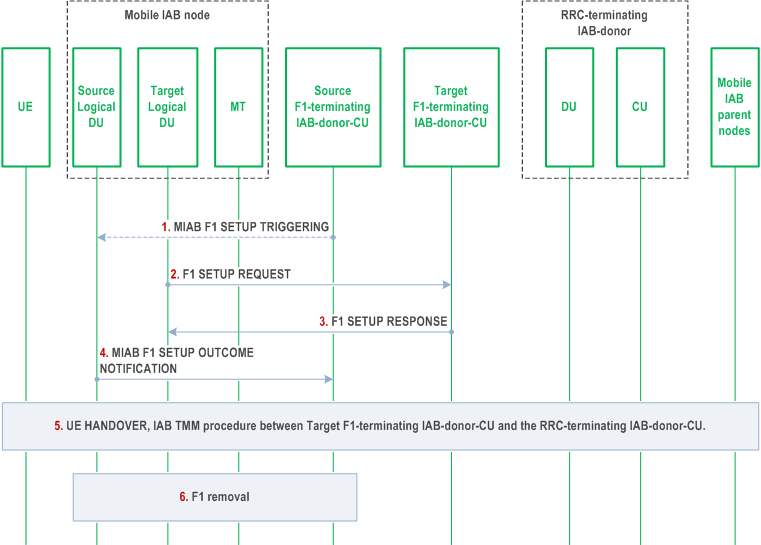
Figure 8.23.3-1 shows an example of the mobile IAB-DU migration procedure. In this example, the source and the target F1-terminating IAB-donor-CUs are different from the RRC-terminating IAB-donor-CU.

Step 1.
The source F1-terminating IAB-donor-CU may send an MIAB F1 SETUP TRIGGERING message to the source logical mobile IAB-DU to initialize the F1 Setup procedure towards the target F1-terminating IAB-donor-CU. The MIAB F1 SETUP TRIGGERING message includes the gNB ID of the target F1-terminating IAB-donor-CU and the information needed to establish the TNL connection with the target F1-terminating IAB-donor-CU for F1-C.
Step 2.
The target logical mobile IAB-DU initiates TNL establishment and F1 setup (as defined in clause 8.5) with the target F1-terminating IAB-donor-CU. During the F1 Setup procedure, the target logical mobile IAB-DU includes the gNB ID of the RRC-terminating IAB-donor-CU, and the BAP address of the co-located mobile IAB-MT in the F1 SETUP REQUEST message.
Step 3.
The target F1-terminating IAB-donor-CU responds to the target logical mobile IAB-DU with an F1 SETUP RESPONSE message. After F1 setup with the target F1-terminating IAB-donor-CU, the target logical mobile IAB-DU can serve UEs via the target mobile IAB-DU's activated cell(s).
Step 4.
By sending the MIAB F1 SETUP OUTCOME NOTIFICATION message, the source logical mobile IAB-DU informs the source F1-terminating IAB-donor-CU about the outcome of the F1 interface setup between the co-located target logical mobile IAB-DU and the target F1-terminating IAB-donor-CU. The source logical mobile IAB-DU may provide the source F1-terminating IAB-donor-CU with a mapping between activated cells of the source logical mobile IAB-DU and activated cells of the target logical mobile IAB-DU. If the mobile IAB-DU migration is triggered by the OAM, the gNB-ID of the target F1-terminating IAB-donor-CU is included in this message.
Step 5.
The source F1-terminating IAB-donor-CU hands over the UE from a source cell served by the source logical mobile IAB-DU to a target cell served by the target logical mobile IAB-DU. The target F1-terminating IAB-donor-CU initiates the IAB Transport Migration Management procedure towards the RRC-terminating IAB-donor-CU for offloading the UE's traffic during this step. In case the IAB Transport Migration Management procedure is the first procedure for the mobile IAB-MT, it includes the mobile IAB-MT's BAP address in the IAB TRANSPORT MIGRATION MANAGEMENT REQUEST message. After the completion of the UE handover, the source F1-terminating IAB-donor-CU requests from the RRC-terminating IAB-donor-CU the release of the UE's traffic offloaded to the RRC-terminating IAB-donor-CU by initiating IAB Transport Migration Management procedure.
Step 6.
After all the UEs are handed over, the source F1-terminating IAB-donor-CU may initiate the removal of the F1 interface towards the source logical mobile IAB-DU.
8.23.4 Mobile IAB-node RLF recovery p. 150
When the mobile IAB-MT detects backhaul RLF, the mobile IAB-MT can perform inter-CU backhaul RLF recovery procedure to another parent node underneath a different IAB-donor-CU. The mobile IAB-DU and the co-located mobile IAB-MT may connect to the same IAB-donor-CU before or after the backhaul RLF recovery, or they may connect to different IAB-donor-CUs before and after the backhaul RLF recovery. In case the mobile IAB-MT and the mobile IAB-DU connect to the same IAB-donors before the backhaul RLF recovery, the procedure is the same as defined in steps 1-18 of the IAB inter-CU backhaul RLF recovery procedure described in clause 8.17.4, where the mobile IAB-node corresponds to the Recovery IAB-node.
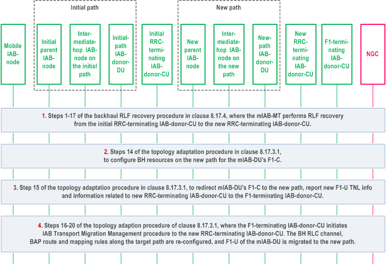
In case the mobile IAB-MT and the mobile IAB-DU connect to different IAB-donor-CUs before and after the backhaul RLF recovery, the procedure for the backhaul RLF recovery is shown in Figure 8.23.4-1.

Step 1.
Steps 1-17 of the backhaul RLF recovery procedure in clause 8.17.4 are performed to conduct backhaul RLF recovery of the mobile IAB-MT from the initial parent IAB-node to the new parent IAB-node. In these steps, the mobile IAB-node corresponds to the recovering IAB-node in clause 8.17.4. The initial and new RRC-terminating IAB-donor-CUs correspond to the initial and new IAB-donor-CUs of clause 8.17.4, respectively.
Step 2.
Step 14 of the topology adaptation procedure in clause 8.17.3.1 is performed to configure BH resources on the new path for the mIAB-DU's F1-C. In this step, the mobile IAB-node corresponds to the migrating IAB-node, the new RRC-terminating IAB-donor-CU corresponds to the target IAB-donor-CU, and the new path of the mobile IAB-node corresponds to the target path in clause 8.17.3.1.
Step 3.
Step 15 of the topology adaptation procedure in clause 8.17.3.1 is performed to redirect the mobile IAB-DU's F1-C to the new path, and report the new F1-U TNL information to the F1-terminating IAB-donor-CU. In this step, the F1-terminating IAB-donor-CU corresponds to the source IAB-donor-CU in clause 8.17.3.1.
During this step, the mobile IAB-DU also passes the gNB ID of the new RRC-terminating IAB-donor-CU and the mobile IAB-node's BAP address allocated by the new RRC-terminating IAB-donor-CU to the F1-terminating IAB-donor-CU.
Step 4.
Same as step 16-20 of the topology adaptation procedure in clause 8.17.3.1, where the F1-terminating IAB-donor-CU initiates IAB Transport Migration Management procedure to the new RRC-terminating IAB-donor-CU to provide the context of the offloaded traffic. The backhaul related configurations along the new path can be re-configured by the new RRC-terminating IAB-donor-CU, and the F1-U connections of the mobile IAB-node are migrated to the new path.