Content for TS 38.401 Word version: 18.4.0
1…
5…
6…
6.1.4
6.1.5…
6.2…
7…
8…
8.2…
8.2.1.4…
8.2.2…
8.2.3…
8.2.4
8.2.5
8.3…
8.4…
8.4.4…
8.5…
8.9…
8.9.4…
8.9.6…
8.9.7…
8.10
8.11…
8.12…
8.13…
8.14…
8.15…
8.15.2…
8.16…
8.17…
8.17.3…
8.17.4
8.18…
8.19…
8.19.2
8.19.3
8.19.4…
8.21…
8.22…
8.23…
8.24…
9…
A…
8.15 Overall procedures for NR MBS
8.15.1 General
8.15.1.1 Broadcast MBS Session Setup
8.15.1.1a Broadcast MBS Session Setup for resource efficiency for MOCN
8.15.1.1b Broadcast MBS Session Setup for resource efficiency for RAN sharing with multiple cell-ID broadcast
8.15.1.2 Multicast MBS Session Context Establishment
8.15.1.3 Multicast MRB type re-configuration with F1-U ptp-retransmission tunnel establishment
...
...
8.15 Overall procedures for NR MBS |R17| p. 102
8.15.1 General p. 102
The following clauses describe the overall procedures for NR MBS involving E1 and F1.
8.15.1.1 Broadcast MBS Session Setup p. 102
Figure 8.15.1.1-1 illustrates an exemplified interaction of NGAP, E1AP, F1AP and RRC protocol functions at Broadcast MBS Session Setup.
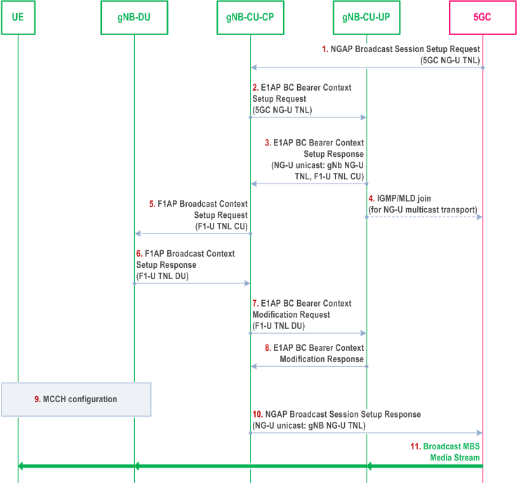
Step 1.
On NG-U, in case of location dependent broadcast MBS Sessions, multiple shared NG-U transport tunnels may need to be setup, one per Area Session ID served by the gNB.
In case of shared NG-U termination,
The 5GC starts the broadcast session by sending the NGAP Broadcast Session Setup Request message to the gNB containing e.g. the TMGI, S-NSSAI, 5G QoS Profile, area information and transport information (for NG-U multicast transport it provides the IP multicast address and the IP source specific multicast address).
Step 2/3.
The gNB-CU-CP sets up the broadcast bearer context, providing NG-U transport information from the 5GC to the gNB-CU-UP, receiving from the gNB-CU-UP the NG-U GTP DL TEID and storing it in case NG-U unicast transport was selected and an F1-U GTP UL TEID per MRB.
Step 4.
In case of NG-U multicast transport, the gNB-CU-UP joins the NG-U multicast group.
Step 5/6.
The gNB-CU-CP establishes the Broadcast MBS Session Context at the gNB-DU, providing e.g. MRB configuration, other relevant session parameters and F1-U GTP UL TEID information, and receiving F1-U GTP DL TEID information.
Step 7/8.
The gNB-CU-CP triggers BC Bearer Context Modification Request towards the gNB-CU-UP to provide the F1-U GTP DL TEID information.
Step 9.
The gNB-DU configures broadcast resources and provides broadcast configuration information to the UEs by means of MCCH.
Step 10.
The gNB-CU CP successfully terminates the NGAP broadcast Session Setup procedure. In case the gNB has chosen NG-U unicast transport, NG-U GTP DL TEID information is provided to the 5GC.
Step 11.
The broadcast MBS media stream is provided to the UEs.
- the gNB-CU-UP may provide the gNB-CU-CP at E1 setup or configuration update about established shared NG-U terminations, indicated by one or several MBS Session IDs.
- at establishment of the BC bearer context in the gNB-CU-UP, the gNB-CU-CP may request the gNB-CU-UP to either apply the available MRB configuration of the shared NG-U termination, or to apply the MRB configuration requested by the gNB-CU-CP. The gNB-CU-UP provides the MRB configuration to the gNB-CU-CP if the MRB configuration requested by the gNB-CU-CP and the available MRB configuration of the shared NG-U termination are different.
8.15.1.1a Broadcast MBS Session Setup for resource efficiency for MOCN |R18| p. 103
Figure 8.15.1.1a-1 illustrates an exemplified interaction of NGAP, E1AP, F1AP and RRC protocol functions at Broadcast MBS Session Setup with the support of resource efficiency for MOCN.
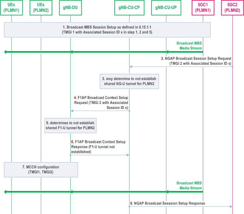
Step 1.
Afterwards, if the gNB-CU-CP decides (e.g., in case the 5GC1 triggers Broadcast Session Release) to establish shared NG-U resources with the 5GC2 with which the shared NG-U was not established:
The 5GC1 triggers the Broadcast MBS Session Setup procedure for TMGI 1 as defined in clause 8.15.1.1, and the Associated Session ID x is provided together with TMGI 1 in step 1, 2 and 5 of clause 8.15.1.1. The broadcast MBS media stream received from 5GC1 is provided to the UEs of PLMN1.
Step 2.
The 5GC2 triggers the Broadcast MBS Session Setup procedure for TMGI 2 with the Associated Session ID x.
Step 3.
Upon receiving the same Associated Session ID x, the gNB-CU-CP may determine to not establish shared NG-U tunnel for PLMN2 with 5GC2, in case of multicast transport, the gNB-CU-CP stores the multicast transport address received from the 5GC2.
Step 4.
The gNB-CU-CP triggers the F1AP Broadcast Context Setup Request for TMGI 2 with the Associated Session ID x towards the gNB-DU.
Step 5.
Upon receiving the same Associated Session ID x, the gNB-DU shall determine to not establish shared F1-U tunnel for PLMN2.
Step 6.
The gNB-DU triggers the F1AP Broadcast Context Setup Response for TMGI 2 to the gNB-CU, and indicates that the shared F1-U tunnel is not established.
Step 7.
The gNB-DU provides configuration of both TMGI 1 and TMGI 2 by means of MCCH. The broadcast MBS media stream received from 5GC1 is provided to both UEs of PLMN1 and UEs of PLMN2.
Step 8.
The gNB-CU-CP sends NGAP Broadcast Session Setup Response towards 5GC2.
- in case of multicast transport, the gNB-CU-CP triggers BC Bearer Context Modification Request towards the gNB-CU-UP providing the stored multicast address received from the 5GC2. Then the gNB-CU-UP joins the NG-U multicast group of 5GC2 accordingly;
- in case of unicast transport, the gNB-CU-CP triggers Broadcast Session Transport Request towards the core network providing the unicast transport address received from the gNB-CU-UP.
8.15.1.1b Broadcast MBS Session Setup for resource efficiency for RAN sharing with multiple cell-ID broadcast |R18| p. 105
Figure 8.15.1.1b-1 illustrates an exemplified interaction of NGAP, E1AP, F1AP and RRC protocol functions at Broadcast MBS Session Setup with the support of resource efficiency for RAN sharing with multiple cell-ID broadcast.
The gNB-DU1/2 entity shown in Figure 8.15.1.1b-1 is a simplified representation of the gNB-DU1 of PLMN 1, the gNB DU2 of PLMN 2 and respective radio resources of the shared cell.
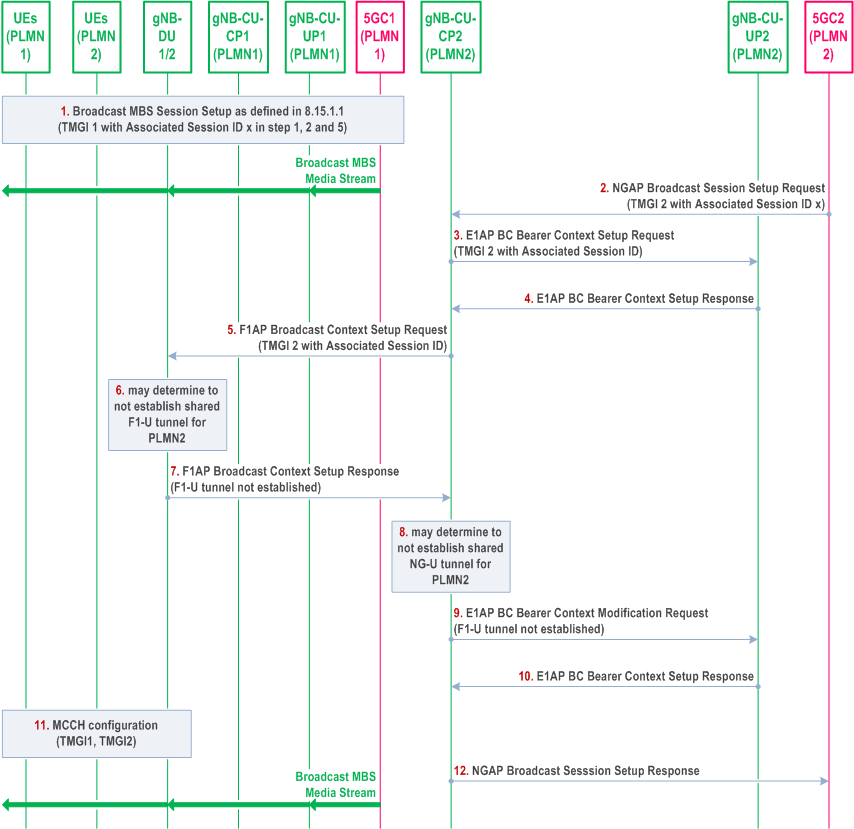
Step 1.
Afterwards, if the gNB-DU1/2 decides (e.g., upon receiving the Broadcast Context Release Command from gNB-CU-CP1 in case the 5GC1 triggers Broadcast Session Release) to establish the shared F1-U tunnel for PLMN2 which was not established:
The 5GC1 triggers the Broadcast MBS Session Setup procedure towards gNB-CU-CP1 for TMGI 1 as defined in section 8.15.1.1, and the Associated Session ID x is provided together with TMGI 1 in step 1, 2 and 5 of 8.15.1.1. The broadcast MBS media stream received from 5GC1 is provided to the UEs of PLMN1 via the gNB-CU-UP1 and the gNB-DU1.
Step 2.
The 5GC2 triggers the Broadcast MBS Session Setup procedure for TMGI 2 with the Associated Session ID x towards gNB-CU-CP2.
Step 3/4.
The gNB-CU-CP2 sets up the broadcast bearer context with gNB-CU-UP2 including the Associated Session ID x. The gNB-CU UP uses the received information to correlate the MBS sessions and include the shared NG-U termination endpoint if applicable.
Step 5.
The gNB-CU-CP2 triggers the F1AP Broadcast Context Setup Request for TMGI 2 with the Associated Session ID x towards the gNB-DU2.
Step 6.
Upon receiving the same Associated Session ID x, the gNB-DU1/2 may determine to not establish shared F1-U tunnel for PLMN2.
Step 7.
The gNB-DU2 triggers the F1AP Broadcast Context Setup Response for TMGI2 to the gNB-CU-CP2, and indicates that the shared F1-U tunnel is not established.
Step 8.
The gNB-CU-CP2 may determine to not establish shared NG-U tunnel for PLMN2. In case of multicast transport, the gNB-CU-CP2 stores the NG-U multicast transport address received from 5GC2 in step 2. In case of unicast transport, the gNB-CU-CP2 stores the NG-U unicast transport address received from the gNB-CU-UP2 in step 4.
Step 9/10.
The gNB-CU-CP2 triggers E1AP BC Bearer Context Modification procedure towards the gNB-CU-UP2, and indicates that the shared F1-U tunnel is not established.
Step 11.
The gNB-DU1/2 provides configuration of both TMGI 1 and TMGI 2 by means of MCCH. The broadcast MBS media stream received from 5GC1 is provided to both UEs of PLMN1 and UEs of PLMN2.
Step 12.
The gNB-CU-CP2 sends NGAP Broadcast Session Setup Response towards 5GC2.
- the gNB-DU2 triggers Broadcast Transport Resource Request towards the gNB-CU-CP2 and providing the F1-U TNL at DU;
- and then, the gNB-CU-CP2 triggers the BC Bearer Context Modification Request towards the gNB-CU-UP2 providing the F1-U TNL at DU,
- in case of multicast transport, the gNB-CU-CP2 also provides the stored NG-U multicast transport address received from 5GC2. Then the gNB-CU-UP2 joins the NG-U multicast group of 5GC2 accordingly;
- in case of unicast transport, the gNB-CU-CP2 triggers the Broadcast Session Transport procedure towards the 5GC2 providing the stored NG-U unicast transport address received from gNB-CU-UP2.
8.15.1.2 Multicast MBS Session Context Establishment p. 106
Figure 8.15.1.2-1 illustrates an exemplified interaction of NGAP, E1AP, F1AP and RRC protocol functions for Multicast MBS Session Context Establishment with a UE joining an active multicast session as the first UE joining in its serving gNB.
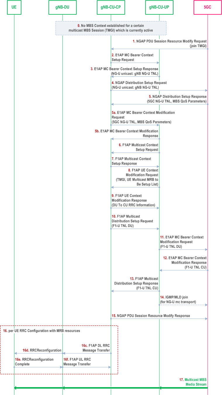
Step 0.
On NG-U, in case of location dependent multicast MBS Sessions, multiple shared NG-U transport tunnels may need to be setup, one per Area Session ID served by the gNB.
In case of shared NG-U termination,
For a certain multicast MBS session (TMGI), which is currently active, no multicast MBS session context is yet established in the gNB.
Step 1.
The UE joins the multicast session.
Step 2/3.
The gNB-CU-CP establishes the multicast bearer context at the gNB-CU-UP. For unicast NG-U transport the GTP DL TEID is retrieved.
Step 4/5.
The gNB-CU CP triggers the NGAP Distribution Setup procedure. For unicast NG-U transport, DL GTP TEID is provided to the 5GC. For multicast NG-U transport, multicast address information is retrieved from the 5GC. Multicast session QoS parameters are provided by the 5GC.
Step 5a/5b.
The gNB-CU-CP triggers the setup of MRB resources via the E1AP MC Bearer Context Modification procedure. For multicast NG-U transport the 5GC shared NG-U multicast address information is provided to the gNB-CU-UP. Multicast session QoS parameters are provided to the gNB-CU-UP.
Step 6/7.
The gNB-CU-CP establishes the Multicast Context at the gNB-DU, providing MRB configuration. It may contain MBS Area Session ID information.
Step 8/9.
The gNB-CU-CP retrieves the MRB configuration for the joined UE from the gNB-DU via F1 UE Context Management procedures.
Step 10.
The gNB-DU triggers the establishment of F1-U resources, which are established either per gNB-DU or per cell or per MBS Area Session ID.
Step 11/12.
The gNB-CU-UP side of the F1-U is established by means of the E1AP MC Bearer Context Modification procedure, providing the gNB-DU side F1-U TNL to the gNB-CU-UP, which provides the gNB-CU-UP side F1-U TNL address in return.
Step 13.
The gNB-CU-UP side F1-U TNL address is provided to the gNB-DU.
Step 14.
In case of NG-U multicast transport, the gNB-CU-UP joins the NG-U multicast group.
Step 15.
The gNB successfully terminates the NGAP procedure for establishing the multicast session context.
Step 16.
The gNB-CU-CP RRC-configures each UE which has joined the multicast group.
Step 17.
The multicast MBS media stream is provided to the UEs.
- the gNB-CU-UP may provide the gNB-CU-CP at E1 setup or configuration update about established shared NG-U terminations, indicated by one or several MBS Session IDs.
- at establishment of the MC bearer context in the gNB-CU-UP, the gNB-CU- CP may request the gNB-CU-UP to either apply the available MRB configuration of the shared NG-U termination, or to apply the MRB configuration requested by the gNB-CU-CP. The gNB-CU-UP provides the MRB configuration to the gNB-CU-CP if the MRB configuration requested by the gNB-CU-CP and the available MRB configuration of the shared NG-U termination are different.
8.15.1.3 Multicast MRB type re-configuration with F1-U ptp-retransmission tunnel establishment p. 108
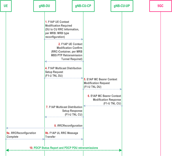
Step 1.
The gNB-DU decides to change the MRB type configuration for a UE and provides the new configuration to the gNB-CU-CP along with a per-MRB MRB type reconfiguration indication and the MRB Reconfigured RLC mode.
Step 2.
The gNB-CU-CP confirms the modification request and indicates this to the gNB-DU. The gNB-CU-CP may request the gNB-DU to establish F1-U ptp retransmission resources in order for the UE to perform PDCP Status Report and receive retransmitted PDCP PDUs for the reconfigured MRBs.
Step 4-7.
If necessary, the gNB-DU requests the establishment of F1-U resources for ptp retransmission by means of triggering the F1AP Multicast Distribution Setup procedure, which in turn triggers the E1AP MC Bearer Context Modification procedure to exchange F1-U tunnel end-point addresses.
Step 8-9.
The RRC Reconfiguration procedure is performed
Step 10.
PDCP Status Report and PDCP PDU retransmission can take place via the established F1-U ptp retransmission resources.