Content for TS 38.401 Word version: 18.4.0
1…
5…
6…
6.1.4
6.1.5…
6.2…
7…
8…
8.2…
8.2.1.4…
8.2.2…
8.2.3…
8.2.4
8.2.5
8.3…
8.4…
8.4.4…
8.5…
8.9…
8.9.4…
8.9.6…
8.9.7…
8.10
8.11…
8.12…
8.13…
8.14…
8.15…
8.15.2…
8.16…
8.17…
8.17.3…
8.17.4
8.18…
8.19…
8.19.2
8.19.3
8.19.4…
8.21…
8.22…
8.23…
8.24…
9…
A…
8.21 Overall procedures for Network Controlled Repeater
8.21.1 Network Controlled Repeater Integration Procedure
...
...
8.21 Overall procedures for Network Controlled Repeater |R18| p. 139
8.21.1 Network Controlled Repeater Integration Procedure p. 139
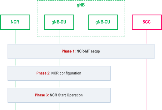
A high-level flow chart for Network Controlled Repeater integration is shown in Figure 8.21.1-1:

Phase 1:
NCR-MT setup. In this phase, the NCR-MT of the Network Controlled Repeater (re-)selects a cell that broadcasts the Network Controlled Repeater supporting information in SIB1. It then connects to the network as a UE, by performing the RRC connection setup procedure with the gNB-CU, and authentication with the 5GC. The NCR-MT includes the Network Controlled Repeater indication in the RRCSetupComplete message. The gNB selects an appropriate AMF for the Network Controlled Repeater. Upon receiving the Network Controlled Repeater authorization information from 5GC, the gNB-CU provides the authorization information to the gNB-DU.
Phase 2:
Network Controlled Repeater configuration. The gNB-CU may configure the Network Controlled Repeater via RRC.
Phase 3:
Network Controlled Repeater Start Operation. After the Network Controlled Repeater is configured, it may start serving the UE(s).