Content for TS 23.060 Word version: 18.0.0
1…
5…
5.3.8…
5.4…
5.4.2…
5.4.9…
5.6…
5.6.2
5.6.3…
5.6.3.7…
5.7…
6…
6.3…
6.5…
6.6…
6.8…
6.9…
6.9.1.3
6.9.2…
6.9.2.2…
6.9.2.2.2
6.9.2.2.3…
6.9.2.2.5…
6.9.3…
6.10…
6.12…
6.13…
6.13.1.2…
6.13.2…
6.13.2.2
6.14…
8…
8.2
9…
9.2.2…
9.2.2.2
9.2.2.3…
9.2.3…
9.2.3.2…
9.2.3.3…
9.2.4…
9.2.4.2…
9.2.5…
12…
12.5…
12.6…
12.7…
12.8…
13…
14…
15…
15.3…
16…
16.2…
A…
B…
12.6 Gb Interface (A/Gb mode)
12.6.1 Physical Layer Protocol
12.6.2 Link Layer Protocols
12.6.3 BSS GPRS Protocol
...
...
12.6 Gb Interface (A/Gb mode) p. 290
The Gb interface connects the BSS and the SGSN, allowing the exchange of signalling information and user data. The Gb interface shall allow many users to be multiplexed over the same physical resource. Resources are given to a user upon activity (when data is sent or received) and are reallocated immediately thereafter. This is in contrast to the A interface where a single user has the sole use of a dedicated physical resource throughout the lifetime of a call irrespective of activity.
A/Gb mode signalling and user data are sent in the same user plane. No dedicated physical resources are required to be allocated for signalling purposes.
Access rates per user may vary without restriction from zero data to the maximum possible line rate (e.g. 1 984 kbit/s for the available bit rate of an E1 trunk).
12.6.1 Physical Layer Protocol p. 290
Several physical layer configurations and protocols are possible, as defined in TS 48.014.
The physical resources shall be allocated by O&M procedures.
12.6.2 Link Layer Protocols p. 290
Several Gb interface link layer configurations and protocols are possible as defined in TS 48.016.
12.6.3 BSS GPRS Protocol p. 290
The primary function of BSSGP is to provide the radio-related, QoS, and routeing information that is required to transmit user data between a BSS and an SGSN. In the BSS, it acts as an interface between LLC frames and RLC/MAC blocks. In the SGSN, it forms an interface between RLC/MAC-derived information and LLC frames. A secondary function is to enable two physically distinct nodes, the SGSN and the BSS, to operate node management control functions.
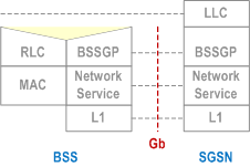
There is a one-to-one relationship between the BSSGP protocol in the SGSN and in the BSS. If one SGSN handles multiple BSSs, the SGSN has to have one BSSGP protocol machine for each BSS. If the BSS applies Intra Domain Connection of RAN Nodes to Multiple CN Nodes, the BSS must have one BSSGP protocol machine for each SGSN to which it applies Intra Domain Connection of RAN Nodes to Multiple CN Nodes.
The main functions of the BSSGP protocol are to:
- provide a connection-less link between the SGSN and the BSS;
- transfer data unconfirmed between the SGSN and the BSS;
- provide tools for bi-directional control of the flow of data between the SGSN and the BSS;
- handle paging requests from the SGSN to the BSS;
- give support for flushing of old messages in the BSS e.g. when an MS changes BSS;
- support multiple layer 2 links between the SGSN and one BSS; and
- Provide tools for control of the flow of data between the SGSN and the BSS during PS Handover procedures, as defined in TS 48.018.
12.6.3.1 Inter-dependency of the BSSGP and LLC Functions p. 291
The functions of the BSSGP shall be defined in the context of the LLC function in order to avoid duplication of functions and information flows. The following functional model indicates each layer's functional responsibilities.
| Network Node and Function | MS | BSS | SGSN |
|---|---|---|---|
| LLC: TS 44.064 | Same as for the SGSN. | Provides transfer of frames between the SGSN and MS. | |
| BSSGP: TS 48.018 | MS←PLMN: Using BSSGP information, RLC/MAC operations are invoked. | Individual MS radio-related information is used by the BSS to transfer LLC frames across the Gb and Um | |
| MS→PLMN: Using RLC/MAC-derived information, a BSSGP PDU is constructed. An identifier of the cell including RAC and LAC in which an LLC frame was received is inserted into the BSSGP PDU. | |||
| Same as for SGSN | Provides flow control and unconfirmed data delivery services across the Gb interface (not the Um - this is the function of the LLC and RLC/MAC function). Provides SGSN-BSS node management functions | ||
| Network Service: TS 48.016 | Same as for SGSN | Provides a multiplexing, variable-bandwidth, frame-based, link layer transport mechanism across the Gb interface, and load balancing. |
12.6.3.2 BSSGP Addressing p. 291
For information transfer between the SGSN and the BSS, the BSSGP is using a BSSGP Virtual Connection Identifier (BVCI) for addressing. Additionally, QoS profile, and the MS identification, e.g. TLLI, may be used to create queues and contexts in both the SGSN and the BSS. The flow control mechanism is then based on these queues and contexts.
12.6.3.3 BVCI Contexts in BSS and in SGSN p. 291
A BVCI context in the BSS consists of at least one queue for LLC PDUs and of the radio resource capacity that is available on a radio cell for one SGSN. If the BSS applies Intra Domain Connection of RAN Nodes to Multiple CN Nodes, the BSS must share the total available radio resource capacity for a radio cell between all the BVCI contexts representing this radio cell, where each of these BVCI contexts represents the radio cell for one SGSN.
The BVCI context in the BSS is allocated for each cell supporting GPRS. For each new GPRS cell introduced in the BSS area, a new BVCI context shall be allocated. If the BSS applies Intra Domain Connection of RAN Nodes to Multiple CN Nodes, the BSS must have for each cell supporting GPRS and belonging to one pool area, one BVCI context for each of the SGSNs associated with this pool area.
In the SGSN, the BVCI context consists of at least one queue for LLC PDUs and the allowed throughput on BSSGP. The allowed throughput is updated by BSSGP flow control messages.
12.6.3.4 Flow Control Between SGSN and BSS over the Gb Interface p. 292
The flow control mechanism controls the loading of the BSS LLC PDU queues per BVCI, per MS and optionally per one or more PFCs between the SGSN and the BSS in the downlink direction. No flow control is performed in the uplink direction. Buffers and link capacity shall be dimensioned to avoid loss of uplink data.
The downlink flow control mechanism is based on the following principles:
- In the SGSN, queues for LLC PDUs are provided per BVCI. These queues may be split further, e.g. per MS or per packet flow. The SGSN shall pass LLC PDUs to LLC via BSSGP to the BSS as long as the allowed BSSGP throughput is not exceeded. The allowed BSSGP throughput is given per BVCI, for a single MS on that BVCI and optionally for one or more PFCs of a single MS on a certain BVCI. The SGSN schedules the BSSGP downlink traffic of all MSs of a BVCI and, optionally of all PFCs of an MS, according to the maximum and guaranteed bit rate attributes and to the QoS profile related to each LLC PDU. The scheduling algorithm is implementation dependent.
- In the BSS, queues per BVCI context are provided at the BSSGP level. These queues may be split further, e.g. per MS or per packet flow. Depending on the queuing conditions and the available radio resource capacity in the cell, the BSS indicates the allowed BSSGP throughput per BVCI context and the default allowed BSSGP throughput for each individual MS of that BVCI context by BSSGP flow control messages to the SGSN. Additionally, the BSS may change the allowed BSSGP throughput for one or more PFCs of an individual MS or for an individual MS by a BSSGP flow control message. As more than one SGSN may send downlink data at the same time for a radio cell when the BSS applies Intra Domain Connection of RAN Nodes to Multiple CN Nodes, the BSS has to share the total possible downlink traffic between the SGSNs that can access a radio cell. The BSS should use the existing flow control procedure on BVCI level to control each of the SGSNs in a way not to violate the total possible traffic for the radio cell. How the BSS decides to share the downlink traffic between each of the SGSNs is an implementation specific issue.
12.6.3.5 BSS Context p. 292
The SGSN may provide a BSS with information related to ongoing user data transmission in A/Gb mode. The information is given as BSS packet flow contexts, which describe QoS characteristics for the data transmission. Network support of BSS packet flow procedures is indicated in the system information as specified in TS 44.060, the MS support is indicated in MS network capability as specified in TS 24.008.
All BSS packet flow contexts related to one MS are stored in an MS specific BSS context. The BSS may contain BSS contexts for several MSs. Within a BSS context the BSS packet flow contexts are identified by a packet flow identifier, which is assigned by the SGSN. A BSS packet flow context is shared by one or more LLC SAPIs of the same MS with identical or similar negotiated QoS profiles. The data transfers related to LLC SAPIs that share the same BSS packet flow context constitute one packet flow.
Four packet flows are pre-defined, and identified by four reserved packet flow identifier values. The BSS shall not negotiate BSS packet flow contexts for these pre-defined packet flows with the SGSN. One pre-defined packet flow is used for best-effort service, one is used for SMS, one is used for TOM (Tunnelling of Messages) and one is used for signalling. The SGSN can assign the best-effort or SMS packet flow identifier to any PDP context. In the SMS case, the BSS shall handle the packet flow for the PDP context with the same QoS with which it handles SMS. A non-reserved packet flow identifier value is only significant for an MS when the SGSN provided the BSS with a packet flow context for this packet flow identifier value for this MS.
The combined BSS QoS profile for the PDP contexts that share the same packet flow is called the aggregate BSS QoS profile. The aggregate BSS QoS profile is considered to be a single parameter with multiple data transfer attributes as defined in clause "Quality of Service Profile". It defines the QoS that must be provided by the BSS for a given packet flow between the MS and the SGSN, i.e. for the Um and Gb interfaces combined. The aggregate BSS QoS profile is negotiated between the SGSN and the BSS. In order to control UE-AMBR, the SGSN shall group all non-GBR PDP contexts for an MS into a single aggregate BBS QoS profile and set the MBR parameter of that profile to equal the UE-AMBR.
A BSS packet flow timer indicates the maximum time that the BSS may store the BSS packet flow context. The BSS packet flow timer shall not exceed the value of the READY timer for this MS. The BSS packet flow timer is started when the BSS packet flow context is stored in the BSS and when an LLC frame is received from the MS. When the BSS packet flow timer expires, the BSS shall delete the BSS packet flow context.
When a PDP context is activated, modified or deactivated, the SGSN may create, modify, or delete BSS packet flow contexts.
PS Handover procedure is used to handover an MS with one or more packet flows from a source cell to a target cell. Handling of the BSS packet flows during PS Handover procedures over the BSSGP are described in TS 43.129 and TS 48.018.
12.6.3.5.1 BSS Packet Flow Context Creation Procedure p. 293
On receiving a request to transmit an uplink or downlink LLC PDU for which no BSS packet flow context exists in the BSS, the BSS may request the download of the BSS packet flow context from the SGSN.
If MS and BSS supports BSS packet flow procedures the SGSN may at any time request the creation of a BSS packet flow context, e.g. due to the activation of a PDP context.
If a request to create a BSS Packet Flow is received in the BSS for an MS during the ongoing PS Handover procedure, then the BSS shall ignore the request and apply the procedures as described in TS 48.018.
The BSS Packet Flow Context Creation procedure is illustrated in Figure 85.
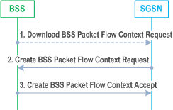
Step 1.
The BSS receives a request to transfer an uplink or downlink user data LLC PDU for which it currently does not have a BSS packet flow context. In the uplink case, TLLI, Radio Priority, and Packet Flow Id are received from the MS as defined in TS 44.060. In the downlink case, TLLI and Packet Flow Id are received from the SGSN as defined in TS 48.018. If Packet Flow Id does not indicate a pre-defined value the BSS sends a Download BSS Packet Flow Context Request (RAI, TLLI, Packet Flow Id) message to the SGSN. Until the BSS receives the BSS packet flow context, the BSS shall handle uplink and downlink transfers according to a default aggregate BSS QoS profile. For uplink transfers, the default profile is specific to the radio priority level.
Step 2.
The SGSN sends a Create BSS Packet Flow Context Request (IMSI, TLLI, Packet Flow Id, Aggregate BSS QoS Profile Requested, BSS Packet Flow Timer) message to the associated BSS. The SGSN derives Aggregate BSS QoS Profile Requested from the QoS profile negotiated for the PDP contexts that share a packet flow as follows: The SGSN shall divide the transfer delay attribute in the QoS profile in one core network part and one BSS part. The SGSN estimates the transfer delay in the core network and subtracts this from the GPRS bearer service transfer delay. The result only covers the delay in the MS to SGSN segment of the GPRS PLMN. Since the BSS transports LLC PDUs obtained after segmentation of SDUs by the SNDCP layer, the SGSN shall convert the values of the GPRS bearer service attributes maximum SDU size, SDU error ratio, residual bit error ration, maximum bit rate, guaranteed bit rate and the resulting transfer delay to values applicable to the LLC PDUs. All other attributes in Aggregate BSS QoS Profile shall be the same as the corresponding GPRS bearer service attribute, see TS 23.107. The SGSN may also include the Allocation / Retention Priority Information Element in the Create BSS Packet Flow Context Request.
Step 3.
The BSS may restrict the requested aggregate BSS QoS profile given its capabilities and the current load. If the Allocation / Retention Priority Information Element is included by the SGSN in the Create BSS Packet Flow Context Request, the BSS may use it to perform queuing of the packet flow context creation or to pre-empt other packet flow contexts. The BSS creates a BSS packet flow context and inserts the parameters in its BSS context. The BSS returns a Create BSS Packet Flow Context Accept (IMSI, Packet Flow Id, Aggregate BSS QoS Profile Negotiated) message to the SGSN. The BSS uses the negotiated aggregate BSS QoS profile when allocating radio resources and other resources such as buffer capacity. The detailed operation is defined in TS 48.018. If the SGSN Aggregate BSS QoS Profile requested by the SGSN was restricted by the BSS, the SGSN takes the BSS restriction into account when indicating to the MS the negotiated QoS of the associated PDP context(s).
12.6.3.5.2 SGSN-Initiated BSS Packet Flow Context Modification Procedure p. 294
The SGSN may at any time request the modification of the contents of an existing BSS packet flow context, e.g. due to the activation, modification, or deactivation of a PDP context, or modification of the UE-AMBR value. The BSS Packet Flow Context Creation procedure shall be used in this case, and the BSS shall instead of creating a BSS packet flow context overwrite the existing parameters with the modified parameters.
The BSS Packet Flow Context Modification procedure will never be initiated for an MS during the ongoing PS Handover procedure as described in TS 48.018.
12.6.3.5.3 BSS-Initiated BSS Packet Flow Context Modification Procedure p. 294
The BSS can at any time request modification of the contents of an existing BSS packet flow context, e.g. due to a change in the resource availability at the BSS.
The BSS-Initiated BSS Packet Flow Context Modification procedure is illustrated in Figure 86.
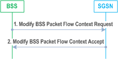
Step 1.
The BSS sends a Modify BSS Packet Flow Context Request (IMSI, Packet Flow Id, Aggregate BSS QoS Profile Requested) message to the SGSN.
Step 2.
The SGSN may restrict the requested aggregate BSS QoS profile given its capabilities and the current load. The SGSN returns a Modify BSS Packet Flow Context Accept (IMSI, TLLI, Packet Flow Id, Aggregate BSS QoS Profile Negotiated, BSS Packet Flow Timer) message to the BSS. The BSS inserts the modified parameters in its BSS context.
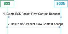
12.6.3.5.4 BSS Packet Flow Context Deletion Procedures p. 294
The BSS may, due to e.g. memory restrictions or user inactivity, at any time delete a BSS packet flow context without notifying the SGSN.
If the BSS is no longer able to support the aggregate BSS QoS profile of a BSS packet flow context, it may, especially for conversational or streaming traffic class, request the SGSN to delete or modify the BSS packet flow context. The SGSN should either modify or delete the BSS packet flow context. In addition the SGSN may need to initiate the PDP Context Modification or PDP Context Deletion procedure.
If a Delete BSS Packet Flow Context Request is received for an MS during the ongoing PS Handover procedure, the procedures applied are described in TS 48.018.
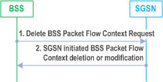
Step 1.
The SGSN may request the deletion of a BSS packet flow context with the SGSN-Initiated BSS Packet Flow Context Deletion procedure, as illustrated in Figure 87.
The BSS sends a Delete BSS Packet Flow Context Request (TLLI, Packet Flow Id, Cause) to the SGSN.
Step 2.
The SGSN should start either the SGSN-initiated BSS packet flow context modification procedure or the deletion of the BSS packet flow context. In addition the SGSN may need to initiate the PDP Context Modification or PDP Context Deletion procedure.
