Content for TS 23.060 Word version: 18.0.0
1…
5…
5.3.8…
5.4…
5.4.2…
5.4.9…
5.6…
5.6.2
5.6.3…
5.6.3.7…
5.7…
6…
6.3…
6.5…
6.6…
6.8…
6.9…
6.9.1.3
6.9.2…
6.9.2.2…
6.9.2.2.2
6.9.2.2.3…
6.9.2.2.5…
6.9.3…
6.10…
6.12…
6.13…
6.13.1.2…
6.13.2…
6.13.2.2
6.14…
8…
8.2
9…
9.2.2…
9.2.2.2
9.2.2.3…
9.2.3…
9.2.3.2…
9.2.3.3…
9.2.4…
9.2.4.2…
9.2.5…
12…
12.5…
12.6…
12.7…
12.8…
13…
14…
15…
15.3…
16…
16.2…
A…
B…
8.2 Radio Resource Functionality (Iu mode) p. 216
8.2.1 Radio Resource Management p. 216
UTRAN functions are defined in TS 25.401. The radio interface protocol architecture is specified in TS 25.301, and the Radio Resource Control protocol is specified in TS 25.331. TS 43.051 contains an overall description of GSM/EDGE Radio Access Network.
In the context of this specification, the term URA refers also to GRA (GERAN Registration Area) when the RAN serving an MS in Iu mode is a GERAN.
8.2.2 RRC State Machine p. 217
The RRC state machine is a description model of how the MS and the Iu mode RAN co-operate regarding RRC functionality. The RRC state describes the MS state in the Iu mode RAN. This clause contains a brief description of the RRC state machine, for more information see TS 25.303.
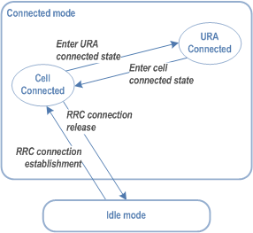
The RRC state machine exists as two peer entities, one in the MS and one in the Iu mode RAN. Apart from transient situations and error cases the two peer entities are synchronised. Figure 57 illustrates the main modes and states of the RRC state machine.

RRC Idle mode:
In the Idle mode there is no connection established between the MS and the Iu mode RAN. There is no signalling between RAN and the MS except for system information that is sent from RAN on a broadcast channel to the MS. The MS can also receive paging messages with a CN identity on the PCH. There is no information of the MS stored in RAN in this mode.
RRC Connected mode:
In the Connected mode the main states are Cell Connected state and URA Connected state. In this mode there is one RNC/BSC that is acting as serving RNC/BSC, and an RRC connection is established between the MS and this SRNC/SBSC.
- When the MS position is known at the cell level, the MS is in the Cell Connected state. When in Cell Connected state, the RRC connection mobility is handled by handover and cell update procedures.
- When the MS position is known at the URA level, the MS is in the URA Connected state. URA updating procedures provide the mobility functionality in this state. No dedicated radio resources are used in the URA Connected state.
8.2.3 Discontinuous Reception p. 217
An MS can set the DRX cycle length that is specific to the PS domain. TS 25.304 describes how the MS shall select which DRX cycle length to use with respect to DRX cycle length requirements set by the RAN, CN PS domain and CN CS domain.
The DRX parameter information shall be indicated by the MS in the attach procedure and when changing from A/Gb mode to Iu mode also in the routeing area update procedure. The SGSN shall then in each page request send these parameters to the RNC/BSC that uses this information, and the IMSI, to calculate the correct paging group.
At inter SGSN change (either RA update or SRNS relocation), the DRX parameters are sent from the old SGSN to the new SGSN as part of the MM context information. Hence, unless the DRX parameters have been altered, the UE should not include the DRX parameters in the Routing Area Update message. There is one other exception to this: in order to support mobility from pre-Release 99 SGSNs, the MS shall include the DRX Parameter IE in a Routing Area Update Request message sent at RA update from GERAN to UTRAN.
At inter-SGSN RA update (e.g. from GERAN), if the network receives a DRX parameters IE from the MS in the routeing area update request message, the new SGSN shall use the information provided by the MS and shall ignore the same IE received in MM Context from the old SGSN.
If the UE wishes to alter its GERAN or UTRAN/E-UTRAN DRX Parameters while in Iu mode, then it shall send a Routing Area Update Request message to the SGSN containing its new DRX Parameters. If ISR had been activated for the MS, then the MS shall deactivate ISR by setting its TIN to "P-TMSI" so that the MS performs a Tracking Area Update when it next enters E-UTRAN coverage. When the UE performs that Tracking Area Update, the MME will receive the updated DRX parameters within the MM context information sent by the old SGSN and hence the UE should not include them again in the Tracking Area Update.
8.2.3a Extended idle mode Discontinuous Reception (DRX) |R13| p. 218
8.2.3a.1 General p. 218
In Iu mode, extended idle mode DRX may be enabled as described in clause 8.1.2a.1.
8.2.4 Paging Initiated by CN p. 218
A CN node requests paging only for MSs in CMM IDLE state or PMM IDLE state. In the separate CN architecture, paging from a CN node is done independently from the state of the MS in the other CN service domain.
In the context of this specification, the terms RNS or RNC refer also to a GERAN BSS or BSC (respectively) when serving an MS in Iu mode.
In this alternative with paging co-ordination in the RAN, the MS does not need to listen to the PCH (Paging Channel) in the RRC Connected mode, at least not when MS is allocated a dedicated channel.
For each paging request received from a CN node, the RNC determines whether the MS has an established RRC connection or not. In order to achieve this, the context that is prepared within the SRNC for MS in RRC Connected mode must contain the IMSI, which is the common MS identity for the two CN domains.
If no context is found for the MS, "normal PCH paging" is performed. The paging message is transferred on the paging channel, and it includes the MS paging identity received from the CN and a CN service domain type indication.
If a context is found, a "CN paging message" is transferred using the existing RRC connection. This message includes a CN service domain type indication. If, potentially after repetition, this transfer is unsuccessful and if the CS domain originally triggered the paging, the RNC should decide whether to attempt "normal PCH paging" as described in clause "Unsynchronous states in the UE and the UTRAN".
8.2.4.1 PS Paging Initiated by SGSN (Iu mode) without RRC Connection for CS p. 218

1)
Optionally, 3G SGSN may include "Non Searching Indication" in RANAP Paging message in this case. If a "Non Searching Indication" parameter is present, the RNC will not search the established RRC connection, and just initiate "normal PCH paging".
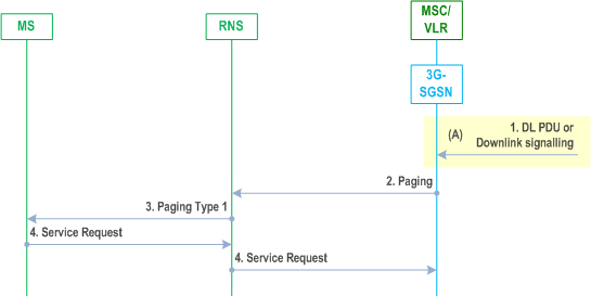
The 3G SGSN receives a DL PDU or downlink signalling for an MS in PMM Idle state.
2)
The 3G SGSN sends a RANAP Paging (IMSI, P-TMSI, Area, CN Domain Indicator, DRX parameters, list of CSG IDs for paging) message to each RNS belonging to the routeing area in which the MS is located. IMSI is needed by the RNS in order to calculate the MS paging group, and to identify the paged MS. If 3G SGSN assigned the P-TMSI to the MS, P-TMSI is also included. Area indicates the routeing area in which the MS is paged. CN Domain Indicator indicates which domain (MSC or 3G SGSN) initiated the paging message, and it represents "SGSN" in this case. DRX Parameters indicates the MS's preferred DRX cycle length. The list of CSG IDs for paging is included when the 3G SGSN is configured to support paging optimisation described in clause 5.3.9. For paging optimisation, the CSG IDs of expired CSG subscriptions and valid CSG subscriptions are both included in the list. If the MS has emergency bearer service the 3G SGSN shall not perform paging optimization.
3)
The RNS controls whether the MS has an established RRC connection or not. In this case, MS has no RRC connection, so a "normal PCH paging" is performed. Paging Type 1(IMSI or P-TMSI, Paging originator, CN domain ID) is transferred on the Paging channel, IMSI or P-TMSI identifies the MS. Paging originator indicates whether this is core network originated paging or RAN originated paging, so it represents "CN" in this case. And CN domain ID indicates whether this paging message is for CS service or PS service, so it represents "PS" in this case.
4)
The paging request triggers the Service Request procedures in the MS. The service request procedures are described in clause "Service Request Procedure (Iu mode)".
8.2.4.1A Serving GW Triggered Paging (Iu mode) with S4 |R8| p. 219

A)
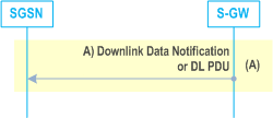
If the S-GW has no downlink user plane TEIDs for S4 and S12, the S-GW buffers the DL PDUs and identifies which SGSN is serving that UE.
If that SGSN has requested the S-GW to throttle downlink low priority traffic and if the downlink data packet is received on a low priority bearer to be throttled (see clause 5.3.6.5), the S-GW drops the downlink data packet. The steps below are not executed.
Otherwise the S-GW sends a Downlink Data Notification to the SGSN.
If the S-GW has downlink user plane TEIDs for S4 the DL PDUs are transferred to SGSN.
8.2.4.2 PS Paging Initiated by 3G-SGSN With RRC Connection for CS p. 220

1)
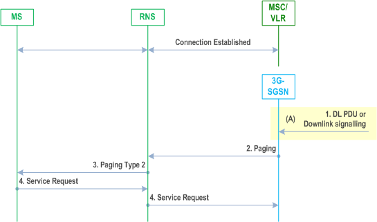
The 3G SGSN receives a DL PDU or downlink signalling for an MS in PMM Idle state.
2)
The 3G SGSN sends a RANAP Paging (IMSI, P-TMSI, Area, CN Domain Indicator, DRX parameters, list of CSG IDs for paging) message to each RNS belonging to the routeing area in which the MS is located. IMSI is needed by the RNS in order to calculate the MS paging group. If 3G SGSN assigned the P-TMSI to the MS, P-TMSI is included, and it identifies the MS is paged. Area indicates the routeing area in which the MS is paged. CN Domain Indicator indicates to which domain (MSC or 3G SGSN) the paging was initiated, and it represents "3G SGSN" in this case. DRX Parameters indicates whether or not the MS uses discontinuous reception and the DRX cycle length. The list of CSG IDs for paging is included when the 3G SGSN is configured to support paging optimisation described in clause 5.3.9. For paging optimisation, the CSG IDs of expired CSG subscriptions and valid CSG subscriptions are both included in the list. If the MS has emergency bearer service the 3G SGSN shall not perform paging optimization.
3)
The RNS controls whether the MS has an established RRC connection or not. In this case, MS has an established RRC connection for CS service, so RNS sends an RRC Paging Type 2 (CN domain ID) message to the MS on established RRC connection. CN Domain ID indicates to which domain (CS or PS) the paging shall be directed, so it represents "PS" in this case.
4)
The paging request triggers the Service Request procedures in the MS. The service request procedures are described in clause "Service Request Procedure (Iu mode)".
8.2.5 Paging Initiated by RAN p. 220
An MS in RRC URA/GRA connected state is paged by the RAN before a downlink transfer to that MS. The URA/GRA paging procedure shall move the RRC state to Cell Connected to allow the RAN to forward downlink data or signalling message to the radio resource. Therefore, the RRC: Cell Update message from the MS that moves the RRC State at the RAN to Cell Connected state is a valid response to URA/GRA paging.
The RAN supervises the paging procedure with a timer. If the RAN receives no response from the MS to the URA or GRA Paging Request message, it shall repeat the paging. The repetition strategy is implementation dependent. If it is unsuccessful and if the paging was originally triggered by the CS domain, it is the RNC's responsibility to recover this situation by following the "normal PCH paging" mechanism (see clause "Paging Initiated by CN"). For more information see TS 25.303.
The URA/GRA Paging procedure is illustrated in Figure 60.

1)
The RAN receives a downlink PDP PDU for an MS in RRC URA/GRA connected state. Downlink signalling to an MS in RRC URA/GRA connected state initiates URA/GRA paging as well.
2)
The RAN pages the MS with one Paging Type 1 (RNTI, Paging originator) message in each cell belonging to the URA/GRA where the MS exists. RNTI is the identifier by which the MS is paged. Paging originator indicates whether this is the core network originated paging or RAN originated paging, so it represents "RAN" in this case.
3)
The paging request triggers the Cell Update procedures in the MS. The Cell Update procedures are described in TS 25.331.