Content for TS 23.433 Word version: 19.4.0
0…
4…
7…
8…
9.2…
9.2.2.3…
9.2.3…
9.2.4…
9.3…
9.3.2.2…
9.3.3…
9.3.4…
9.4…
9.5…
9.5.3…
9.5.4…
9.6…
9.7…
9.7.3…
9.7.4…
9.8…
9.9…
9.9.3…
9.10…
9.10.3…
9.11…
9.11.3…
9.12…
9.12.3…
9.13
10…
A…
C
D…
9.8 SEALDD enabled rate control for VAL applications
9.8.1 General
9.8.2 Procedures
9.8.2.1 SEALDD enabled bandwidth control for different VAL users
9.8.2.2 SEALDD enabled congestion control for VAL applications
9.8.3 Information flows
9.8.4 APIs
...
...
9.8 SEALDD enabled rate control for VAL applications p. 91
9.8.1 General p. 91
The following clauses specify procedures, information flows and APIs for SEALDD enabled rate control transmission.
9.8.2 Procedures p. 91
9.8.2.1 SEALDD enabled bandwidth control for different VAL users |R19| p. 91
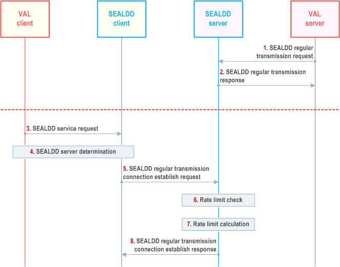
The SEALDD layer can provide the differentiated data delivery service with different bandwidth experience for VAL users, where the VAL server can provide the bandwidth limit (i.e., minimum bandwidth requirement and maximum bandwidth limit) for VAL users. Figure 9.8.2.1-1 illustrates the procedure for bandwidth control for different VAL users.
Pre-conditions:
- The VAL server has discovered and selected the SEALDD server by CAPIF functions as specified in clause 9.4.2.
- The SEALDD server has subscribed to 5GC for QoS monitoring of the specific UE related to the VAL user, as defined in clause 5.2.6.9 in TS 23.502.
- The SEALDD policy (i.e, the bandwidth control policy) has been configured in SEALDD server, as described in clause 9.10.

Step 1.
If the connection establishment is rejected, the SEALDD client can re-establish SEALDD connection by performing steps 5-8, when the pending timer is expired.
For the uplink application traffic, the SEALDD client can buffer or drop some packets when the uplink traffic from VAL client exceeds the suggested traffic transmission bandwidth. Similarly, for the downlink application traffic, the SEALDD server can buffer or drop some packet when the downlink traffic from VAL server exceeds the suggested traffic transmission bandwidth.
The VAL server sends a Sdd_regularTransmission request to the SEALDD server. The request includes the identifiers of the application traffic (e.g. VAL service ID, VAL server ID), the VAL server's total bandwidth limit and the bandwidth limits (i.e. minimum bandwidth requirement and maximum bandwidth limit) for VAL users.
Step 2.
Upon receiving the request, the SEALDD server performs an authorization check. If authorization is successful, the SEALDD server sends a response to the VAL server.
Step 3.
The VAL client sends a SEALDD service request to SEALDD client.
Step 4.
The VAL/SEALDD client discover and select the proper SEALDD server for the VAL application. After this step, the VAL server is discovered and selected along with the associated SEALDD server, the SEALDD client can get the SEALDD server's address.
Step 5.
The SEALDD client sends Sdd_RegularTransmissionConnection_Establish request to SEALDD server with the SEALDD client ID, the VAL user or UE identity, XR application device capability information as per Table 9.2.3.3-1. The SEALDD client can retrieve the capability information as per the clause 9.2.3 and clause 9.2.6 of TS 26.118.
Step 6.
The SEALDD server performs bandwidth limit check according to the VAL user's bandwidth limit, the current SEALDD traffic delivery status, the VAL server's total bandwidth limit and/or the related UE's current network status (i.e. via QoS monitoring report from the 5GC). If the available bandwidth (i.e. the remaining bandwidth that can be used for the VAL user without exceeding the VAL server's total bandwidth limit) cannot meet the VAL user's minimum bandwidth requirement, the SEALDD server will reject the SEALDD client's connection establishment request.
Step 7.
When the available bandwidth can meet the VAL user's requirement, the SEALDD client can establish the SEALDD connection with the SEALDD server. The SEALDD server can calculate the suggested traffic transmission bandwidth to the SEALDD client according to the VAL user's bandwidth limit and the related UE's current network status (i.e. via QoS monitoring report or ECN marking for L4S report from the 5GC) and XR application device capability information (e.g., codec).
Step 8.
If the bandwidth limit check is failed (i.e., the available bandwidth cannot meet the VAL user's minimum bandwidth requirement) in step 6, the SEALDD server can send Sdd_RegularTransmissionConnection_Establish response with the failed result (i.e., reject the connection establishment) and the pending timer to trigger the re-connection from SEALDD client. If the bandwidth limit check is successful (i.e., the available bandwidth can meet the VAL user's requirement) in step 6, the SEALDD server can send Sdd_RegularTransmissionConnection_Establish response with the successful result and/or the suggested traffic transmission bandwidth.
9.8.2.2 SEALDD enabled congestion control for VAL applications |R19| p. 92
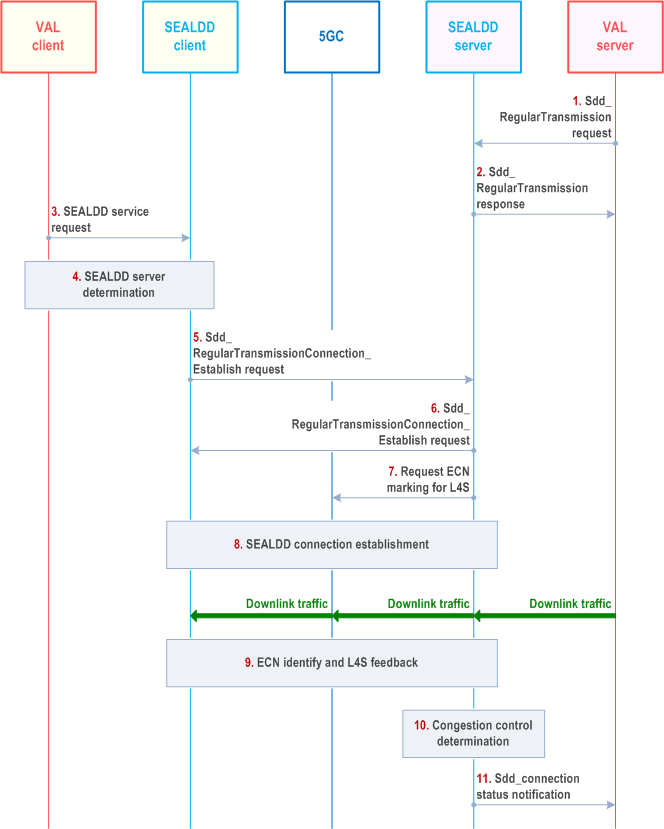
Based on the congestion information exposed by 5GS (i.e., by using ECN marking for L4S), the SEALDD server can perform the differentiated congestion control for multiple VAL applications, after receiving the L4S feedback from the SEALDD client. Figure 9.8.2.2-1 illustrates the procedure for SEALDD enabled congestion control for VAL applications.
Pre-conditions:
- The VAL server has discovered and selected the SEALDD server by CAPIF functions as specified in clause 9.4.2.

Step 1-6.
Same as clause 9.2.2.2 step 1 to step 7 with difference that in step 5 the SEALDD client includes also L4S feedback capability in Sdd_RegularTransmissionConnection_Establish request.
Step 7.
If the L4S feedback capability is received in step 5, the SEALDD server can request 5GC to perform the ECN marking for L4S for the required VAL applications by utilizing the AF session with required QoS procedure in clause 4.15.6.6 of TS 23.502.
Step 8.
Same as step 9 of clause 9.2.2.2.
Step 9.
For downlink traffic, if ECN marking is identified, the L4S feedback is performed in transport layer.
Step 10.
After receiving the L4S feedback in step 9, the SEALDD server may perform the congestion mitigation for downlink traffics from multiple VAL applications. For the same UE, the SEALDD server can determine differentiated congestion control/rate control with the calculated congestion level or the calculated transmission rate for multiple VAL applications based on internal policy considering the received QoS requirements of different VAL applications identified by VAL service ID in step 1.
Step 11.
[Optional] The SEALDD server sends Sdd_connection status notification to VAL server with the calculated congestion level for the VAL service.
9.8.3 Information flows p. 93
See clause 9.2.3 for the details of information flow.
9.8.4 APIs p. 94
See clause 9.2.4 for the details of API.