Content for TS 23.433 Word version: 19.4.0
0…
4…
7…
8…
9.2…
9.2.2.3…
9.2.3…
9.2.4…
9.3…
9.3.2.2…
9.3.3…
9.3.4…
9.4…
9.5…
9.5.3…
9.5.4…
9.6…
9.7…
9.7.3…
9.7.4…
9.8…
9.9…
9.9.3…
9.10…
9.10.3…
9.11…
9.11.3…
9.12…
9.12.3…
9.13
10…
A…
C
D…
9.7 SEALDD enabled data transmission quality measurement
9.7.1 General
9.7.2 Procedures
9.7.2.1 Data transmission quality measurement
9.7.2.2 Data transmission quality query
9.7.2.3 Data transmission quality measurement reported by SEALDD client
...
...
9.7 SEALDD enabled data transmission quality measurement p. 77
9.7.1 General p. 77
The following clauses specify procedures, information flows and APIs for SEALDD enabled data transmission quality measurement.
9.7.2 Procedures p. 77
9.7.2.1 Data transmission quality measurement p. 77
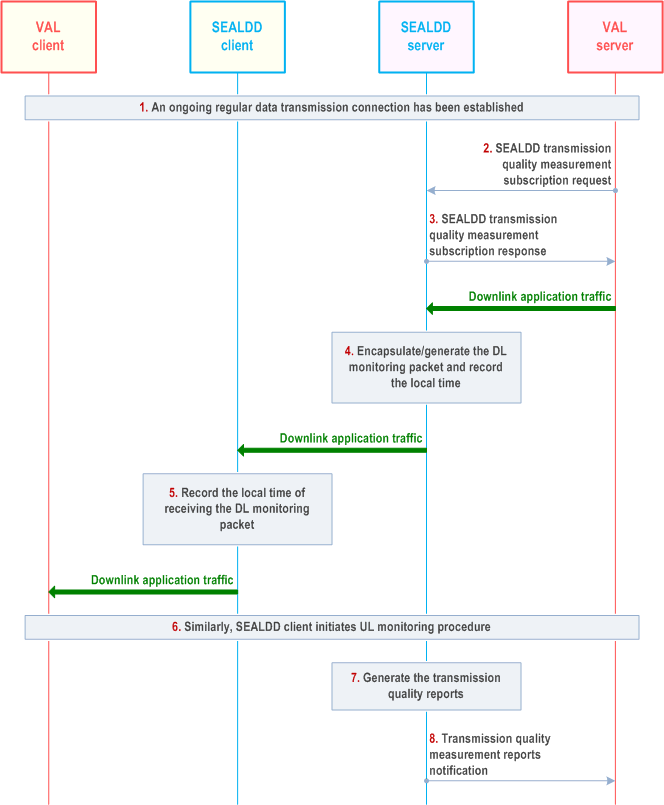
Figure 9.7.2.1-1 illustrate the procedure for SEALDD enabled data transmission quality measurement. The SEALDD client and SEALDD server is enhanced to carry out the data transmission quality measurement.
Pre-conditions:
- The SEALDD server and SEALDD client are synchronized to the time source provided by 5GS as specified in TS 23.501.
- The VAL server discovers and selects the SEALDD server by CAPIF functions.

Step 1.
When a VAL group ID or a list of VAL UE IDs or all VAL UEs indication is received in step 2, step 4 to step 7 is repeated for VAL UEs in the group/list or for all VAL UEs. The SEALDD server maps the VAL UE group ID to a list of VAL UE IDs if a VAL group ID is received. The SEALDD server identifies SEALDD connections corresponding to the desired VAL UE(s) or flow(s) traffic descriptor(s) to trigger measurement. And depending on the reporting requirement for multiple UEs, the SEALDD server calculates the needed report for the VAL server. When the VAL server decides to update or unsubscribe transmission quality measurement subscription after performing step 2 and step 3, the VAL server can send data transmission quality measurement subscription update request and data transmission quality measurement unsubscribe request to SEALDD server, as specified in Table 9.7.3.9-1 and Table 9.7.3.11-1, respectively.
An on-going regular data transmission connection is established according to clause 9.2.2.2.
Step 2.
The VAL server sends a SEALDD transmission quality measurement subscription request to the SEALDD server. The request includes the identifiers of the application traffic (e.g. VAL service ID, VAL server ID), requirement of transmission quality measurement (e.g. latency, jitter, bitrate, packet loss rate) and measurement target UE (e.g. a single UE, a group of UEs or all UEs), flow(s) traffic descriptor(s), and may also include reporting criteria, reporting frequency, spatial condition and temporal condition.
Step 3.
Upon receiving the request, the SEALDD server performs an authorization check. If authorization is successful, the SEALDD server sends a response to the VAL server with the subscription ID, expiration time.
Step 4.
If the transmission quality measurement requirement list provided by VAL server in step 2, indicates that the latency is needed to be measured, the SEALDD server initiates the DL packet delay measurement. The SEALDD server encapsulates the DL monitoring packet (i.e. DL SEALDD packet with SEALDD DL monitoring header and VAL traffic as payload, or dummy DL SEALDD packet generated for data transmission quality monitoring) with local time T1 when the SEALDD server sends out the DL monitoring packets. The SEALDD server considers the spatial and/or temporal conditions when starting/resuming the transmission quality measurement. If the conditions are not satisfied, the SEALDD server stops/suspends the transmission quality measurement.
Step 5.
The SEALDD client receives the DL monitoring packet, and records the local time T2. If the endpoint for the SEALDD traffic is located at the tethered device, the SEALDD client in 5G UE measures the QoS between the SEALDD client in 5G UE and the SEALDD client (i.e. for architecture that has the SEALDD client on the tethered device) or the VAL client (i.e. for architecture that without the SEALDD client on the tethered device) in tethered device, e.g., the SEALDD client may measure the tethered link delay using the ICMP ping protocol as defined in RFC 792). The detailed procedures of Tethering link measurement and provisioning is defined in clause 9.12.2.3.
Step 6.
Similarly, the SEALDD client encapsulates the UL monitoring packet (i.e. UL SEALDD packet with SEALDD UL monitoring header and VAL traffic as payload, or dummy UL SEALDD packet generated for data transmission quality monitoring) with local time T2 recorded in step 5 and local time T3 when the SEALDD client sends out the UL monitoring packet. If the endpoint for the VAL traffic is located at the tethered device, the measurement delay in the tethered link (step 5) is considered in T2 and T3 timestamps, e.g., T2 timestamp includes the half of the measurement delay and T3 timestamp excludes the half of the measurement delay.
Step 7.
The SEALDD server records the local time T4 when the SEALDD server receives the UL monitoring packet and calculates the latency with T1, T2, T3, T4. The SEALDD server can also calculate the bitrate, jitter and packet loss rate over a certain period over a specific SEALDD connection by recording the status of the SEALDD packets carrying VAL traffic or dummy SEALDD packets generated for transmission quality measurement reports. The SEAL DD server also evaluates the reporting criteria if present in the SEALDD transmission quality measurement subscription request in order to generate the transmission quality measurement report.
Step 8.
The SEALDD server reports the data transmission quality measurement results (e.g. latency, jitter, bitrate, packet loss rate) to the VAL server via the notification message.
9.7.2.2 Data transmission quality query p. 79
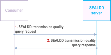
Figure 9.7.2.2-1 illustrate the procedure for SEALDD enabled data transmission quality query. This procedure is used to obtain the historical transmission quality result already measured as described in clause 9.7.2.1.
Pre-conditions:
- The SEALDD server performs the data transmission quality measurement procedure, as described in clause 9.7.2.1.

Step 1.
The consumers (e.g. VAL server, SEALDD server, NSCE server, ADAE server) can send a SEALDD transmission quality query request to the SEALDD server to obtain the transmission quality measurement result. The request includes the identifiers of the application traffic (e.g. VAL service ID, VAL server ID), VAL UE ID or VAL UE group ID, flow(s) traffic descriptor(s), or crossflow measurement information.
Step 2.
The SEALDD server responds with the transmission quality measurement result (e.g. packet delay, bitrate, packet loss rate).
9.7.2.3 Data transmission quality measurement reported by SEALDD client p. 80
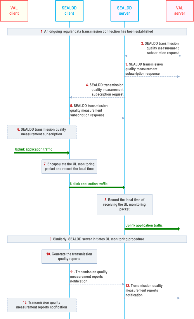
Figure 9.7.2.3-1 illustrate the procedure for SEALDD enabled data transmission quality measurement for VAL traffic. The SEALDD client receives transmission quality measurement requirement, decides to start VAL data transmission monitoring and generates measurement reports.

Step 1.
When a VAL group ID or a list of VAL UE IDs or all VAL UEs indication is received in step 2, step 4 to step 11 is repeated for VAL UEs in the group/list or for all VAL UEs. The SEALDD server maps the VAL UE group ID to a list of VAL UE IDs if a VAL group ID is received. The SEALDD server identifies SEALDD connections corresponding to the desired VAL UE(s) to trigger measurement. And depending on the reporting requirement for multiple UEs, the SEALDD server collects and aggregates the needed report for the VAL server.
An on-going regular data transmission connection is established according to clause 9.2.2.2.
The transmission quality measurement can be triggered by VAL server or VAL client, which is described in step 2 to step 5 and step 6, correspondingly.
The request may include the crossflow measurement information (e.g. {[traffic descriptor 1, UL]; [traffic descriptor 2/DL]}) associated in the same multi-modal service for crossflow RTT measurement.
The detailed procedures of Tethering link measurement and provisioning is defined in clause 9.12.2.3.
Step 2.
The VAL server sends a SEALDD transmission quality measurement subscription request to the SEALDD server. The request includes the identifiers of the application traffic (e.g. VAL service ID, VAL server ID), requirement of transmission quality measurement (e.g. latency, jitter, bitrate) and measurement target UE (e.g. a single UE, a group of UEs or all UEs), and may also include reporting criteria, reporting frequency, spatial condition and temporal condition.
Step 3.
Upon receiving the request, the SEALDD server performs an authorization check. If authorization is successful, the SEALDD server responds to the VAL server.
Step 4-5.
The SEALDD server sends a SEALDD transmission quality measurement subscription request to the SEALDD client and the SEALDD client responds to the SEALDD server. The SEALDD client, based on the received service quality guarantee policy including thresholds and action, can take corrective action as described in clause 9.7.2.3.
If crossflow RTT measurement requirement is received from the VAL server, the SEALDD server identifies the SEALDD connections for the involved VAL UEs and sends to the SEALDD client(s) with crossflow RTT measurement requirement including corresponding UL/DL flow information.
The SEALDD server sends the Non-3GPP access measurement information in the SEALDD transmission quality measurement subscription request to the SEALDD client.
Step 6.
The VAL client triggers the SEALDD transmission quality measurement procedure to the SEALDD client, in order to collect the measurement report information.
Step 7.
After SEALDD client determines to start measurement process, upon UL packet arrival, the SEALDD client initiates the UL packet delay measurement. The SEALDD client encapsulates the UL monitoring packet (i.e. UL SEALDD packet with SEALDD UL monitoring header and VAL traffic as payload for VAL data transmission quality monitoring) with local time T1 when the SEALDD client sends out the UL monitoring packet. The SEALDD client considers the spatial and/or temporal conditions when starting/resuming the transmission quality measurement. If the conditions are not satisfied, the SEALDD client stops/suspends the transmission quality measurement.
For crossflow RTT measurement, the SEALDD client received UL flow information starts recording local time T1 when sending out the 1st UL packet matching the UL flow information to the SEALDD server. The T1 is sent in the encapsulated UL monitoring packet to the SEALDD server.
Step 8.
The SEALDD server receives the UL monitoring packet, and records the local time T2.
Step 9.
Similarly, the SEALDD server encapsulates the DL monitoring packet (i.e. DL SEALDD packet with SEALDD DL monitoring header and VAL traffic as payload, or dummy UL SEALDD packet generated for data transmission quality monitoring in case there is no DL VAL traffic for DL packet delay monitoring) with local time T2 recorded in step 8 and local time T3 when the SEALDD server sends out the DL monitoring packet.
For crossflow RTT measurement, when the 1st DL packet matching the received DL flow information is to be sent, the SEALDD server encapsulates the DL monitoring packet with previously received T1 and sends the DL monitoring packet to the SEALDD client.
Step 10.
The SEALDD client records the local time T4 when the SEALDD client receives the DL monitoring packet and calculates the latency with T1, T2, T3, T4. The SEALDD client can also calculate the bitrate and jitter over a certain period over a specific SEALDD connection by recording the status of the SEALDD monitoring packets. The SEALDD client also evaluates the reporting criteria and the flow alignment reporting criteria if present in the SEALDD transmission quality measurement subscription request in order to generate the transmission quality measurement report.
For crossflow RTT measurement, if T1 is received in the DL packet, the SEALDD client records local time T2 and calculates RTT based on T1 and T2.
Depending on which entity triggers the data transmission quality measurement, step 11 and step 12 corresponds to step 2 to step 5, step 13 corresponds to step 6.
For the Non-3GPP access measurement, if the Non-3GPP access measurement information includes list of WLAN SSIDs, then the SEALDD client performs the signal strength measurement for the requested WLAN SSID. If the request contains location-based measurement then the SEALDD client measures the signal strength of nearby WLAN SSIDs based on its location.
If the delay difference, i.e., the bound of the difference of the end-to-end time delay among all associated flows, is requested, the SEALDD client calculates the delay difference between VAL server and SEALDD client, based on the arrival time and the timestamp (e.g., timestamp as recorded in the RTP header) among all associated flows identified by the Multi-modal SEALDD flow ID. The arrival time of first detected flow and last detected flow, Ta and Tb, are recorded, and the delay difference is the difference between Ta and Tb. Then SEALDD client sends the calculated delay difference to the SEALDD server.
Step 11-12.
The SEALDD client reports the data transmission quality measurement results (e.g. latency, jitter, bitrate) to the VAL server via the SEALDD server. The report also includes the list of WLAN SSIDs and their signal strength measurements (like RSRP, RSRQ, SINR, RSSI). The Measurement range indicate the scope of the measurement, e.g., end to end measurement, tethering link measurement etc.
Step 13.
The SEALDD client reports the data transmission quality measurement results to the VAL client.