Content for TS 23.280 Word version: 19.5.0
1…
5…
6
7…
8…
9…
10…
10.1.5…
10.2…
10.2.6…
10.3…
10.6…
10.7…
10.7.3.8…
10.8…
10.9…
10.9.3.9…
10.10…
10.10.3
10.11…
10.12…
10.13…
10.14…
10.15…
10.16…
10.17…
10.18…
10.19…
11…
11.5…
A…
B…
C…
E…
10.7 Use of MBMS transmission
10.7.1 General
10.7.2 Information flows for MBMS transmission
10.7.3 Procedures for MBMS usage
10.7.3.1 Use of pre-established MBMS bearers
10.7.3.2 Use of dynamic MBMS bearer establishment
10.7.3.3 Switching from MBMS bearer to unicast bearer
10.7.3.4 Use of MBMS bearer for application level control signalling
10.7.3.5 MBMS bearer announcement over MBMS bearer
10.7.3.6 MBMS bearer quality detection
10.7.3.7 Service continuity in MBMS scenarios
...
...
10.7 Use of MBMS transmission p. 139
10.7.1 General p. 139
This subclause defines information flows and procedures for MBMS usage that applies to MC services. MBMS bearers can be used by any MC service for any MC service group. A single MBMS bearer can be used for one or more MC services within a single group or by multiple group communications in parallel.
The following subclauses specify the procedures and information flows for the usage of MBMS transmission that are utilised by the following MC services:
MC service specific pre-requisites and resultant behaviour by functional entities in performing these procedures are specified in the respective MC service TSs as listed above.
10.7.2 Information flows for MBMS transmission p. 139
10.7.2.1 MBMS bearer announcement p. 139
Table 10.7.2.1-1 describes the information flow MBMS bearer announcement from the MC service server to the MC service client.
| Information element | Status | Description |
|---|---|---|
| TMGI | M | TMGI information |
| Alternative TMGI | O | A list of additional alternative TMGI may be included and used in roaming scenarios. |
| QCI | O | QCI information used by the ProSe UE-Network Relay to determine the ProSe Per-Packet Priority value to be applied for the multicast packets relayed to Remote UE over PC5 |
| List of service area identifier | M | A list of service area identifier for the applicable MBMS broadcast area. |
| Frequency | O | Identification of frequency if multi carrier support is provided |
| SDP information | M | SDP with media and floor control information applicable to groups that can use this bearer (e.g. codec, protocol id, FEC information) |
| Monitoring state | O | The monitoring state is used to control if the client is actively monitoring the MBMS bearer quality or not. |
| Announcement acknowledgment | O | Indicate if the MC service server requires an acknowledgement of the MBMS bearer announcement. |
| ROHC information | O | Indicate the usage of ROHC and provide the parameters of the ROHC channel to signal to the ROHC decoder. |
|
NOTE
When MBMS bearer announcement is done on a MBMS bearer all attributes above are optional except the TMGI.
|
||
10.7.2.2 MBMS listening status report p. 140
Table 10.7.2.2-1 describes the information flow for the MBMS listening status report from MC service client to MC service server. The information is used for the decision on the switching from MBMS bearer to unicast bearer or vice versa.
| Information element | Status | Description |
|---|---|---|
| MC service ID | M | The identity of the MC service user who wants to report the MBMS listening status. |
| TMGI(s) | M | TMGI(s) information. |
| MBMS listening status(s) | M | The MBMS listening status per TMGI. |
| MBMS reception quality level | O | The reception quality level per TMGI (see NOTE) |
|
NOTE:
The set of quality levels helps service continuity in MBMS scenarios. A reception quality level may help to make an efficient switching decision to another bearer. How these levels are used is implementation specific.
|
||
10.7.2.3 MBMS suspension reporting instruction p. 140
Table 10.7.2.3-1 describes the information flow for the MBMS suspension reporting instruction from MC service server to MC service client in a unicast bearer for MBMS suspension reporting.
| Information element | Status | Description |
|---|---|---|
| MC service ID | M | The MC service identity |
| Suspension reporting | M | Enables or disable the suspension reporting for a specific MC service client |
Table 10.7.2.3-2 describes the information flow for the MBMS suspension reporting instruction from MC service server to MC service client in a multicast bearer for MBMS suspension reporting.
| Information element | Status | Description |
|---|---|---|
| Suspension reporting client subset | M | Contains a uniquely defined subset of MC service clients that shall report MBMS suspension |
10.7.2.4 Discover bearer request p. 141
Table 10.7.2.4-1 describes the information flow discover bearer request from the MC service server to another MC service server (MBMS bearer control role).
| Information element | Status | Description |
|---|---|---|
| List of service area identifiers | M | A list of service area identifier for the applicable MBMS broadcast area. |
| Bandwidth | M | Maximum bandwidth required |
| QCI | O | Desired QCI |
10.7.2.5 Discover bearer response p. 141
Table 10.7.2.5-1 describes the information flow discover bearer response from an MC service server (MBMS bearer control role) to the MC service server.
| Information element | Status | Description |
|---|---|---|
| TMGIs | M | List of TMGIs and related information |
| List of service area identifiers | M | A list of service area identifiers for the applicable MBMS broadcast areas, corresponding to the listed TMGIs, over which the request was successful. |
| Frequency | O | Identification of the frequency if multi-carrier support is provided |
| QCI | O | QCI information used by the ProSe UE-Network relay to determine the ProSe per-packet priority value to be applied for the multicast packets relayed to a remote UE over PC5. |
10.7.2.6 Media distribution request p. 141
Table 10.7.2.6-1 describes the information flow media distribution request from the MC service server to an MC service server (MBMS bearer control role) that has a desired bearer.
| Information element | Status | Description |
|---|---|---|
| TMGI | M | TMGI information |
| Bandwidth | M | Maximum bandwidth required |
| Separate floor control | M | Whether or not a separate bearer is required for floor control |
| SDP information | M | SDP with media and floor control information applicable to groups that can use this bearer (e.g. codec, protocol id) |
| QCI | O | Desired QCI |
| MC Group ID | O | The MC group id for when the request is sent for a specific group call. |
10.7.2.7 Media distribution response p. 142
Table 10.7.2.7-1 describes the information flow media distribution response from an MC service server (MBMS bearer control role) that has a desired bearer to the MC service server.
| Information element | Status | Description |
|---|---|---|
| TMGI | M | TMGI information |
| Bandwidth | M | Maximum bandwidth required |
| SDP information | M | SDP with media and floor control information applicable to groups that can use this bearer (e.g. codec, protocol id) |
| QCI | O | Actual QCI |
| Media stream identifier | O | This element identifies the media stream of the SDP used for the group call (e.g. MBMS subchannel). |
| Media distribution indicator | O | Indicates to the MC service server whether the media in the ongoing group communication should be sent or not |
10.7.2.8 Identify multicast participants request p. 142
Void
10.7.2.9 Remove call from bearer request p. 142
Void
10.7.2.10 Media distribution release |R15| p. 142
Table 10.7.2.10-1 describes the information flow media distribution release from the MC service server to an MC service server (MBMS bearer control role) that has the used bearer.
| Information element | Status | Description |
|---|---|---|
| TMGI | M | TMGI information |
| Bandwidth | M | The bandwidth released by the MC service server that used the bearer |
| MC Group ID | O | The MC group id for when the request is sent for a specific group call. |
10.7.2.11 Media broadcasting notification |R15| p. 142
Void.
10.7.2.12 Group status notification |R16| p. 142
Table 10.7.2.12-1 describes the information flow for the group status notification from MC service server to MC service client.
| Information element | Status | Description |
|---|---|---|
| MC service group ID | M | The MC service group ID of the group |
| Status of the group | M | Indicate the group has on-going call or not |
10.7.2.13 MBMS suspension report |R17| p. 143
Table 10.7.2.13-1 describes the information flow for the MBMS suspension report from MC service client to MC service server.
| Information element | Status | Description |
|---|---|---|
| MC service ID | M | The identity of the MC service user who wants to report the MBMS suspension status. |
| TMGI(s) | M | TMGI(s) information. |
| MBMS suspension status(s) | M | The MBMS suspension status per TMGI. |
10.7.3 Procedures for MBMS usage p. 143
10.7.3.1 Use of pre-established MBMS bearers p. 143
10.7.3.1.1 General p. 143
In this scenario, the MC service server pre-establishes MBMS bearer(s) in certain pre-configured areas before the initiation of the group communication session. When a user originates a request for a group communication session for one of these areas, the pre-established MBMS bearer(s) is used for the DL media transmission.
The following steps needs to be performed prior the start of the MC group communication session over pre-established MBMS bearer:
- MBMS bearer(s) is Pre-established
- Announce the pre-established MBMS bearer to the MC service clients
10.7.3.1.2 Procedure p. 143
The procedure Figure 10.7.3.1.2-1 shows only one of the receiving MC service clients using an MBMS bearer. There might also be MC service clients in the same MC group communication session that receive the communication on unicast bearers.
Pre-conditions:
- The participating users are already affiliated.
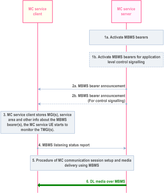
Step 1a.
The MC service server determines to activate MBMS bearer. The activation of the MBMS bearer is done on the MB2-C reference point and according to TS 23.468. This bearer will be used for the MC communication media.
Step 1b.
Optionally, the MC service server may also activate an MBMS bearer dedicated for application level control signalling. The activation of the MBMS bearer is done on MB2-C reference point and according to TS 23.468.
Step 2a.
The MC service server passes the MBMS bearer info for the service description associated with the pre-established MBMS bearer to the MC service client. The MC service client obtains the TMGI, identifying the MBMS bearer, from the service description.
Step 2b.
The MC service server may pass the MBMS bearer info for the service description associated with the pre-established floor control MBMS bearer to the MC service client. The MC service client obtains the TMGI, identifying the MBMS bearer, from the service description.
Step 3.
The MC service client stores the information associated with the TMGI(s). The MC service client uses the TMGI and other MBMS bearer related information to activate the monitoring of the MBMS bearer by the MC service UE.
Step 4.
The MC service client that enters or is in the service area of at least one announced TMGI indicates to the MC service server that the MC service client is able to receive media over MBMS, whereby the MC service server may decide to use the MBMS bearer instead of unicast bearer for MC communication sessions.
Step 5.
An MC service group communication session is established.
Step 6.
As the MC service server transmits the media over the MBMS bearer, the media packets are detected and delivered to the MC service client.
10.7.3.2 Use of dynamic MBMS bearer establishment p. 145
In this scenario depicted in Figure 10.7.3.2-1, the MC service server uses a unicast bearer for communication with the UE on the DL at the start of the group communication session. When the MC service server decides to use an MBMS bearer for the DL media transmission, the MC service server establishes an MBMS bearer using the procedures defined in TS 23.468. The MC service server provides MBMS service description information associated with MBMS bearer(s), obtained from the BM-SC, to the UE. The UE starts using the MBMS bearer(s) to receive DL media and stops using the unicast bearer for the DL media transmission.
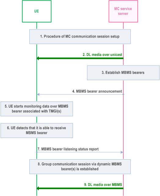
Step 1.
An MC service group communication session is established.
Step 2.
The downlink data is sent by unicast delivery.
Step 3.
The MC service server establishes the MBMS bearer(s) for the group communication session according to the procedures defined in TS 23.468. Service description associated with the MBMS bearer(s) is returned from the BM-SC.
Step 4.
The MC service server provides service description information associated with the MBMS bearer to the UE. The MC service UE obtains the TMGI from the announcement message. This message may be sent on an application level control signalling bearer.
Step 5.
The MC service UE starts monitoring data over MBMS associated with the TMGI, while in the service area associated with the TMGI.
Step 6.
The MC service UE detects that it is able to receive data over MBMS associated with the TMGI.
Step 7.
The MC service client notifies the MC service server the MBMS listening status associated to the monitored TMGI, (e.g. that it is successfully receiving the TMGI). The MC service client may also notify the MBMS reception quality level of the TMGI. MC service server stops sending media data over unicast way to the MC service client.
Step 8.
An MC service group communication session via dynamic MBMS bearer(s) is established.
Step 9.
MC service server sends the downlink media for the group communication session over the MBMS.
10.7.3.3 Switching from MBMS bearer to unicast bearer p. 146
Figure 10.7.3.3-1 shows the procedure for service continuity when a UE is about to move out of MBMS coverage by switching from MBMS bearer to unicast bearer.
Pre-conditions:
- It is assumed that the MBMS bearer has been activated by MC service server for downlink delivery.
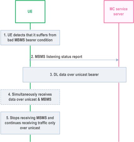
Step 1.
The MC service UE detects that it suffers from bad MBMS bearer condition for the corresponding MBMS service. The method to detect is implementation specific.
Step 2.
The MC service client notifies the MC service server that it suffers from bad MBMS bearer condition for the corresponding MBMS service by sending the MBMS listening status report.
Step 3.
The MC service server sends the downlink data by unicast delivery to the MC service client.
Step 4.
During the switching, the MC service client simultaneously receives downlink data through both unicast bearer and MBMS bearer. If there is no downlink data to the MC service client, this step can be skipped.
Step 5.
The MC service client ceases to receive the downlink data through MBMS bearer but continues receiving data through unicast bearer.
10.7.3.4 Use of MBMS bearer for application level control signalling p. 147
10.7.3.4.1 Description p. 147
The MC service server may use an MBMS bearer for application level control signalling, according to this subclause. An MBMS bearer for application level control signalling is typically used for the purposes beyond the benefit for using MBMS for resource efficiency, e.g. for improved MC service performance (KPIs), handling of high load scenarios.
The MBMS bearer for application level control signalling may be used to transmit the following messages:
- Transmission control (e.g. call setup and floor control)
- MBMS bearer announcement for media bearers
- Group application paging
- Group dynamic data (e.g. status of the group)
- Group state (e.g. emergency alerts)
10.7.3.4.2 Procedure p. 147
The procedure in Figure 10.7.3.4.2-1 shows only one of the receiving MC service clients using an MBMS bearer.
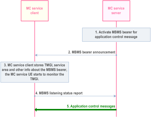
Step 1.
The MC service server determines to activate MBMS bearer for application level control signalling, The activation of the MBMS bearer is done on the MB2-C reference point and according to TS 23.468.
Step 2.
The MC service server passes the MBMS bearer info for the service description associated MBMS bearer to the MC service client. The MC service client obtains the TMGI, identifying the MBMS bearer, from the service description.
Step 3.
The MC service client stores the information associated with the TMGI. The MC service client uses the TMGI and other MBMS bearer related information to activate the monitoring of the MBMS bearer by the MC service UE.
Step 4.
The MC service client that enters or is in the service area of the announced TMGI indicates to the MC service server that the MC service client is able to receive application level control messages over the MBMS bearer. The MC service client may also indicate at which MBMS reception quality level it has received the MC service media on the MBMS bearer. Hence, the MC service server may decide to use the MBMS bearer for MC application control messages.
Step 5.
The MC service server transmit MC application control messages
10.7.3.5 MBMS bearer announcement over MBMS bearer p. 148
10.7.3.5.1 Description p. 148
The MBMS announcement may be done on either a unicast bearer or a MBMS bearer. Using a unicast bearer for MBMS bearer announcement provides an interactive way of doing announcement. The MC service server will send the MBMS bearer announcement message to the MC service client regardless if there is an MBMS bearer active or the MC service client can receive the data on the MBMS bearer with sufficient quality. The benefit of the existing procedure is that it gives a secure way to inform the MC service client about the MBMS bearer and how to retrieve the data on the MBMS bearer.
When there is more than one MBMS bearer active in the same service area for MC service, there are not the same reasons to use unicast bearer for additional MBMS bearer announcement. Instead a MBMS bearer for application level control signalling can be used to announce additional MBMS bearers.
The MBMS bearer announcement messages are sent on an MBMS bearer used for application control messages. This bearer will have a different QoS setting compared to an MBMS bearer used for media, since application signalling messages are more sensitive to packet loss.
10.7.3.5.2 Procedure p. 148
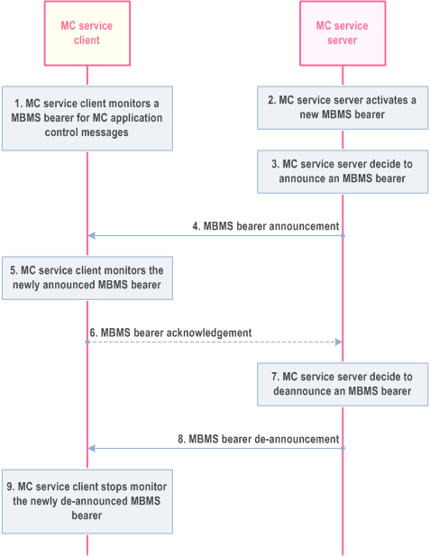
The procedure defined below enables the MC service to announcement a new MBMS bearer.
Pre-conditions:
- An MBMS bearer used for MC service application control messages must have been pre-established and announced to the MC service client.
- Additional MBMS bearer information may have already been announced to the client.
Step 1.
The same procedure can also be used to modify existing MBMS bearer announcement information. Example of such modification could be addition of UDP ports or modification of codec in the SDP.
The MC service client monitors an MBMS bearer that is used for MC service application signalling messages, such as bearer announcement messages.
Step 2.
The MC service server activates a new MBMS bearer.
Step 3.
The MC service server announce the MBMS bearer to the MC service client. The bearer may have just been activated or may have already been running for some time. The step may be repeated as needed.
Step 4.
The MC service server sends a MBMS bearer announcement on the MBMS bearer used for MC application control messages. The MBMS bearer announcement contains the identity of the MBMS bearer (i.e. the TMGI) and may optionally include additional information about the newly announced bearer. Required and optional MBMS bearer announcement details may have already been provided. In this case the MBMS bearer identity could be used as a key for such MBMS bearer details.
Step 5.
The MC service clients start to monitor the newly announced MBMS bearer.
Step 6.
If requested by the MC service server, the MC service client sends an acknowledgement of the MBMS bearer to the MC service server.
Step 7.
The MC service server de-announce the MBMS bearer.
Step 8.
The MC service server sends a MBMS bearer de-announcement message that contains the identity of the MBMS bearer.
Step 9.
The MC service client stops monitoring the de-announced MBMS bearer.
10.7.3.6 MBMS bearer quality detection p. 150
10.7.3.6.1 Description p. 150
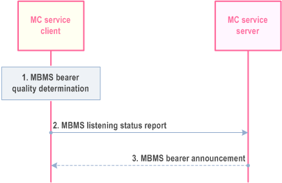
The MC service client and MC service server use this procedure to report and take action on the MBMS bearer quality. An MC service client monitors an MBMS bearer to receive MC service media. Based on the received quality (e.g. radio level quality, transport level quality), the MC service client needs to inform the MC service server that the MC service client is able to receive the MC service media on the MBMS bearer with sufficient quality or not able to receive the MC service media on the MBMS bearer with sufficient quality. Furthermore, based on the received quality, the MC service client may notify the MC service server at which MBMS reception quality level it has received the MC service media on the MBMS bearer.
The issue can be more complex since the MC service client needs to estimate the quality of the bearer even in the scenario when there are no data currently transmitted on the MBMS bearer (e.g. between MCPTT group call). The reason for this is that an MC service client that has entered an area with significantly degraded MBMS quality, might not even notice that an MC service communication is ongoing, meanwhile the MC server still assumes that the MC service client can receive the media being broadcasted.
To estimate the MBMS bearer quality, for example as an equivalent BLER (Block Error Rate), when no data is sent is implementation specific. This estimation can be dependent on for example the modulation and coding scheme (MCS) and measurements from the reference signals from the eNB(s). Other metrics (e.g. RTP packet loss) may be used to estimate the MBMS bearer quality.
10.7.3.6.2 Procedure p. 150
The MC service client shall indicate the ability of the MC service client to receive the MBMS bearer.
Pre-conditions:
- There is an MBMS bearer activated and the MBMS bearer information is announced to the MC service client
- The MC service client is located in the MBMS broadcasting area
- The MC service UE monitors SIB-13 (or SIB-20) and (SC-)MCCH to receive the modulation and coding scheme
- The MC service UE monitors the cell specific reference signal and when MBSFN transmission is used, the MBSFN specific reference signals
Step 1.
The MC service client determines that the MBMS bearer quality shall be reported to the MC service server. The MC service client may determine the MBMS bearer quality by using the BLER of the received data. When no data is received, the quality estimation can consider the reference signals and the modulation and coding scheme (MCS). The UE may also use predictive methods to estimate the expected MBMS bearer quality (e.g. speed and direction) to proactively inform the MBMS service server of an expected loss of the MBMS bearer quality. The MC service client may also map the determined MBMS bearer quality to a MBMS reception quality level. The MBMS reception quality level indicates at which specific MBMS bearer quality level the MC service media has been received. Based on the MBMS reception quality level, the MC service server may efficiently decide to switch to another bearer or to take measures to prepare such a switch.
Step 2.
If the MBMS bearer quality reaches a certain threshold, the MC service client sends an MBMS listening status report. The threshold is used to define the MBMS listening status, which indicates if the MBMS bearer quality has been acceptable or not to receive a specific MC service media. If the MBMS bearer quality is mapped to a different MBMS reception quality level, the MC service client may send an MBMS listening status report including the MBMS reception quality level.
Step 3.
The MC service server may send additional proposal for measurements e.g. information about neighbouring MBMS bearers. This message may be an MBMS bearer announcement message.
10.7.3.7 Service continuity in MBMS scenarios p. 151
10.7.3.7.1 General p. 151
This subclause specify service continuity scenario when MBMS bearers are used. There are different solutions for different scenarios.
10.7.3.7.2 Service continuity when moving from one MBSFN to another p. 151
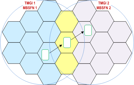
The service continuity solution described in this subclause is suitable in the scenario when multiple MBMS bearers are used with the purpose to cover a larger area. In mission critical communication several media streams may be multiplexed in one MBMS bearer. Furthermore, one media stream (e.g. MCPTT group call) may be sent on more than one MBMS bearer if the receiving users are distributed over more than one MBMS service area. An MC service client that is interested in receiving a media stream that is broadcasted in both MBMS bearers is a candidate for this service continuity procedure.
Figure 10.7.3.7.2-1 illustrates a deployment scenario that provides service continuity between two MBSFN areas. Two different MBMS bearers are activated (TMGI 1 and TMGI 2), the activation of the bearers is done in the two MBSFN areas (MBSFN 1 and MBSFN 2). The MBSFN areas 1 and 2 are partially overlapping, meaning that some transmitting cells belong to both MBSFN area 1 and MBSFN area 2.
The procedural steps will work as follows:
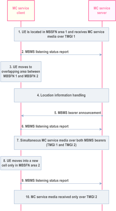
Step 1.
This service continuity procedure mitigates the risk of packet loss that may occur if the UE would request to transfer the media stream to a unicast bearer when moving into the new area and then back to a multicast bearer when the UE can listen to TMGI 2. However, it is still required that the MC service client sends a location report (and MBMS listening report), as described in steps 4-6 above. To send the location report and the MBMS listening report by the MC service client to the MC service server a unicast bearer is needed. The location report from the MC service client is required, since the MC service server must know that the UE has entered a new area and can only listen to MBMS bearer active in that area. If this is not done the MC service server might send a media stream that the MC service client is required to listen to on the MBMS bearer 1, since the MC service server still assumes that the UE is located in the MBSFN area 1.
The solution can be improved as illustrated in Figure 10.7.3.7.2-3. In this case two different MBMS bearers are activated (TMGI 1 and TMGI 2), these MBMS bearers are used only for media. An application level signalling bearer is activated (TMGI 9), in both MBSFN areas. This bearer is used for floor control messages and other application level signalling messages that are sent on the MBMS bearer TMGI 9. A similar concept was already introduced in TS 23.179 subclause 10.10.2, where the procedure allowed a separate MBMS bearer for floor control signalling. The application level signalling bearer will be used for all control messages needed for both media MBMS bearer (TMGI 1 and TMGI2).
By using an application level signalling bearer (e.g. TMGI 9) the MC service clients can receive floor control messages for all calls going on in the areas of both TMGI 1 and TMGI 2. A MC service client that is located in the area of TMGI 2 and is interested in a MCPTT group call transmission only going on in TMGI 1, can with the information received in TMGI 9 initiate a unicast bearer and request to receive that specific call over a unicast instead. Without the information received over TMGI 9 the MC service client must immediately report that the MC service client has left the broadcast area that the MC service server assumes that the MC service client is located in. With the use of TMGI 9 there is no immediate need for the MC service client to inform the MC service server of a location change.
The UE is located in MBSFN 1 and can listen to TMGI 1. No additional MBMS bearers that the MC service client is interested in are active in the current cell.
Step 2.
The MC service client notifies the MC service server that it is successfully receiving the MC service media over TMGI 1. The MC service client may also notify the MBMS reception quality level of TMGI 1.
Step 3.
The UE moves into a new cell in which both TMGI 1 and TMGI 2 are active. This cell is part of both MBSFN area 1 and MBSFN area 2, and broadcast the same service on both TMGIs.
Step 4.
Location information are provided from the MC service UE via the Location management client to the Location management server. For that, the MC service UE uses the SAI information found in the system information block (SIB) transmitted by the radio cells. The location management server provides the location information to the MC service server.
Step 5.
The MC service server sends to the MC service client a MBMS bearer announcement with information related to TMGI 2 (if the MC service server had not done it before). Hence, the MC service client knows that TMGI 2 transmits the same MC service media.
Step 6.
The MC service client notifies the MC service server that it is successfully receiving TMGI 1 and TMGI 2. The MC service client may also notify the MBMS reception quality level per TMGI.
Step 7.
The MC service client may receive the MC service media over both MBMS bearers, i.e. TMGI 1 and TMGI 2. The MC service client may also verify that it is the same content sent on both bearers. The duplicated packets may also be used to perform error corrections.
Step 8.
The UE moves into a new cell in MBSFN area 2, where only TMGI 2 is active.
Step 9.
The MC service client notifies the MC service server that it is successfully receiving the MC service media over TMGI 2. The MC service client may also notify the MBMS reception quality level of TMGI 2.
Step 10.
The MC service client receives the MC service media only over TMGI 2.
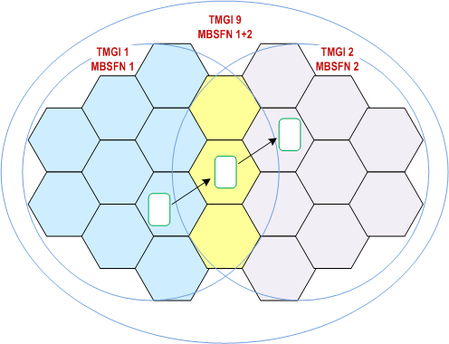
The procedural steps in this scenario will be the same as described above in this subclause. However, in this scenario the MC service client is not required to initiate a unicast bearer to send location report (or MBMS listening report). The UE may move between the two MBMS bearers (TMGI 1 and TMGI 2) without the need to report an area change. A condition for this to work is that there is an application level signalling bearer (TMGI 9) activated in the full area (i.e. the area of both TMGI 1 and TMGI 2). The TMGI 9 will broadcast all floor control messages for all calls ongoing in both areas. If the UE is in coverage of one of the two MBMS bearers that does not transmit the media of interest the UE can report to the server that it is not able to listen to the media over the MBMS bearer, which triggers the server to use a unicast bearer instead.
10.7.3.7.3 Service continuity with a UE-to-Network relay p. 154
This procedure handles a scenario when UE is moving from a location when the UE is experiencing good reception of the MBMS bearer to a location outside the MBMS service coverage. The MC service client apply a service continuity procedure to ensure that the service can be maintained and that the packet loss can be minimized during transition to a UE-to-Network relay connection. The solution also provides the benefit that it offloads the cell when UEs that normally would trigger a transfer from MBMS bearers to unicast bearers when moving outside the MBMS coverage area.
Figure 10.7.3.7.3-1 below illustrates the concept of this procedure. In the Figure UE A (with the MC service client) is first within the MBMS coverage (the far right most location). The MBMS coverage is represented by the dashed circle. The UE A is the moving outside the MBMS coverage and first enters a location in which the MBMS signal is not good enough, but in this location there is still coverage to use unicast bearers. Unicast bearers use link adaption and retransmission so the coverage area for unicast bearers is larger than the coverage of the MBMS bearers. The solid circle outer line represents the coverage of the unicast bearer.
A UE that is leaving the area of MBMS coverage may in this scenario trigger a ProSe discovery procedure to initiate the establishment a relay communication path to UE-R. A UE that is receiving media over an MBMS bearer (and is in idle mode) and for the moment does not need a unicast bearer is costly (from a resource efficiency point of view) to transfer to a unicast bearer due to the need for retransmissions and robust coding in the outer part of cell.
When the ProSe communication path is established the UE A may continue to receive the media over the relay UE-R.
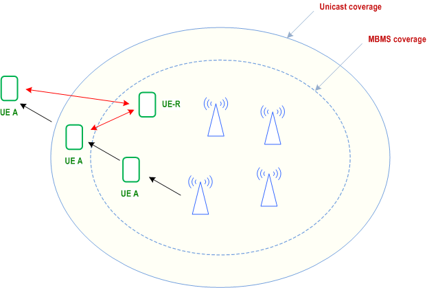
The procedure defined in this subclause allows for MBMS bearer service continuity when UE is moving from a MBMS coverage area to outside the MBMS coverage area. The procedure applies when the UE is not finding a target cell with good RSRP/RSRQ (receiving strong reference signals from other cells), which could trigger normal cell reselection procedure. In such scenario other aspects should be evaluated to trigger to a relay communication path.
Pre-conditions:
- The MC service client UE is not using a unicast bearer when this procedure applies.
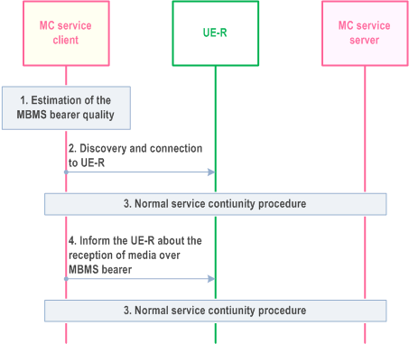
Step 1.
The MC service client estimate the MBMS bearer quality. The MC service clients also measure the reference signals from other cells to estimate the possibilities to transfer to unicast and perform a cell reselection procedure.
Step 2.
If the MBMS bearer quality has reach a certain threshold the MC service client performs ProSe UE-to-network relay discovery over PC5 and establishes a secure point-to-point link with the relay (UE-R) over PC5. As part of this process the remote UE is mutually authenticated at PC5 layer with either the relay or with the network as specified in TS 23.303.
Step 3.
Normal service continuity procedure for a UE-to-network relay. This may be done according to Annex B.
Step 4.
The MC service client informs the UE-R about the reception of media over the MBMS bearer. This includes sending the TMGIs, MBMS SAIs and ProSe per packet priority to the UE-R. This procedure is specified in TS 23.303.
Step 5.
The UE-R will relay the MBMS media using one-to-many ProSe Direct Communication. The UE-R may also relay requests to transfer the media flow from multicast to unicast and vice versa.