Content for TS 23.280 Word version: 19.5.1
1…
5…
6
7…
8…
9…
10…
10.1.5…
10.2…
10.2.6…
10.3…
10.6…
10.7…
10.7.3.8…
10.8…
10.9…
10.9.3.9…
10.10…
10.10.3
10.11…
10.12…
10.13…
10.14…
10.15…
10.16…
10.17…
10.18…
10.18.3…
11…
11.5…
A…
B…
C…
E…
9 Application of functional model to deployments
9.1 General
9.2 Architecture model and deployment scenarios for on-network operations
9.2.1 On-network architectural model
9.2.2 Deployment scenarios
9.3 Architecture model for off-network operations
9.4 Architecture model for roaming
...
...
9 Application of functional model to deployments p. 62
9.1 General p. 62
This clause describes the application of the functional model, described in clause 7, to on-network and off-network deployments. It also describes deployment scenarios that highlight some of the possible variations in the way that the functional model can be applied in different situations.
9.2 Architecture model and deployment scenarios for on-network operations p. 63
9.2.1 On-network architectural model p. 63
9.2.1.1 On-network architectural model diagram p. 63
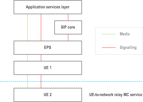
Figure 9.2.1.1-1 below is the on-network architectural model for the MC system solution, where the MC system provides one or more MC services via a single PLMN.
9.2.1.2 Application services layer p. 63
9.2.1.2.1 Overview p. 63
The application services layer includes application functions of one or more MC services and any required supporting functions grouped into common services core.
9.2.1.2.2 Common services core p. 63
Common services core is composed of the following functional entities:
- for common services, a configuration management server as described in subclause 7.4.2.2.2, a group management server as described in subclause 7.4.2.2.4, an identity management server as described in subclause 7.4.2.2.6 and a key management server as described in subclause 7.4.2.2.8; and
- for signalling control, an HTTP proxy as described in subclause 7.4.3.3.2 and an HTTP server as described in subclause 7.4.3.3.3.
9.2.1.2.3 MC services p. 64
MC services are composed of the following functional entities:
- an MC service server as described in subclause 7.4.2.3.2 with relevant application functions of the corresponding MC service defined in the corresponding MC service TS.
9.2.1.3 SIP core p. 64
The SIP core provides rendezvous (contact address binding and URI resolution) and service control (application service selection) functions. It is composed of the following functional entities:
- for signalling control, a local inbound / outbound proxy as described in subclause 7.4.3.1.3.2, a registrar finder as described in subclause 7.4.3.1.3.3 and a registrar / application service selection entity as described in subclause 7.4.3.1.3.4.
9.2.1.4 EPS p. 64
The EPS provides point-to-point and point-to-multipoint bearer services with QoS.
9.2.1.5 UE 1 p. 64
UE 1 is:
- an MC service UE in on-network mode supporting bearer services and application(s) related to one or more MC service;
- an MC service UE that acts as ProSe UE-to-network relay; or
- both of the above.
9.2.1.6 UE 2 p. 64
UE 2 is a device using ProSe UE-to-network relay, and supporting application(s) related to one or more MC services. It is composed of the following functional entities:
- for common services, a group management client as described in subclause 7.4.2.2.3, a configuration management client as described in subclause 7.4.2.2.1, an identity management client as described in subclause 7.4.2.2.5 and a key management client as described in subclause 7.4.2.2.7;
- for MC services, MC service clients as described in subclause 7.4.2.3.1 with relevant application functions of the corresponding MC service defined in the corresponding MC service TS; and
- for signalling control, a signalling user agent as described in subclause 7.4.3.1.1 and an HTTP client as described in subclause 7.4.3.3.1.
9.2.2 Deployment scenarios p. 64
9.2.2.1 Administration of MC service, SIP core and EPS p. 64
9.2.2.1.1 General p. 64
This subclause describes five different deployment scenarios in which different administration of MC service, SIP core and EPS are described, together with the sensitivities of identities and other forms of signalling in those scenarios.
In each of these scenarios, the owner of the devices at each plane may be different from the organisation that administers these devices. For example, the MC service provider may own some RAN components within the EPS even when the EPS is administered by the PLMN operator, and the MC service UE may be owned by an organisation that is independent from PLMN and MC service providers.
9.2.2.1.2 Common administration of all planes p. 65
In this scenario, all planes (application services layer, SIP core and EPS) are administered by the same party. This is illustrated in Figure 9.2.2.1.2-1 below.
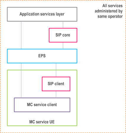
Although the identities in each plane are separate according to clause 8, there is no particular sensitivity of identities and other information at the application plane, and these may be exposed to the SIP core and the EPS.
All authorisation and authentication mechanisms at each plane, i.e. the application services layer, SIP core and EPS, shall be separate, but there may be no need for any restrictions in how these are stored and managed; for example the same entity could provide services to each of the application services layer, SIP core and EPS.
9.2.2.1.3 MC service provider separate from SIP core and EPS p. 65
In this scenario, as illustrated in Figure 9.2.2.1.3-1, the MC service provider is separate and independent from the PLMN operator, and the MC service is administered independently of the EPS and SIP core. The PLMN operator administers the EPS and the SIP core.
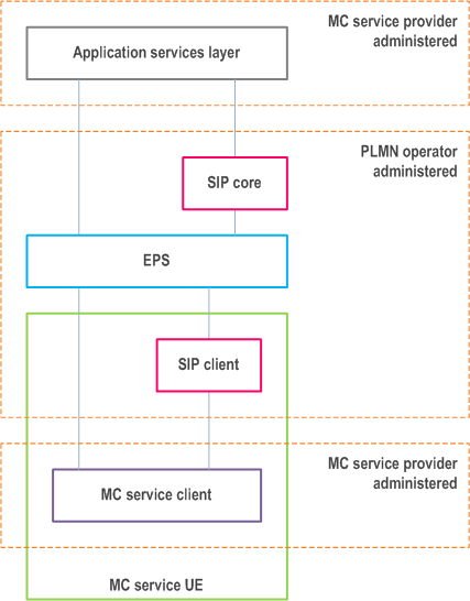
The MC service provider may require that all application services layer identities and other sensitive information are hidden both from the SIP core and the EPS.
When required by the MC service provider, all authentication and authorisation mechanisms, including security roots, at the application services layer are hidden from and not available to the PLMN operator.
9.2.2.1.4 MC service provider administers SIP core, separate from EPS p. 66
In this scenario, as illustrated in Figure 9.2.2.1.4-1, the MC service provider administers the SIP core, and the MC services and SIP core are independent of the PLMN operator.
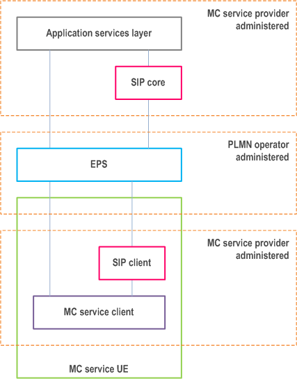
The MC service provider may require that all identities and other sensitive information at the application services layer are hidden from the EPS. The MC service provider need not hide the identities and signalling at the application services layer from the SIP core. However the MC service provider may require that identities and other sensitive information between SIP core and SIP client in the MC service UE are also hidden from the EPS.
All authentication and authorisation mechanisms, including security roots, at both application services layer and at SIP signalling plane may need to be hidden from, and not available to, the PLMN operator.
The HSS-IMS and HSS-EPS in this deployment scenario is across two different administrative domains, then IMS features such as, e.g., T-ADS (TS 23.237) related to service continuity between on-network and UE-to-network relay as in Annex B, NPLI (TS 23.228) related to lawful interception, and P-CSCF restoration (TS 23.380) are not supported.
9.2.2.1.5 SIP core partially administered by both PLMN operator and MC service provider p. 67
In this scenario, as illustrated in Figure 9.2.2.1.5-1, the SIP core is partially administered by both parties, for example when the SIP core registrar is administered by the MC service provider, but the SIP core registrar finder and proxy is administered by the PLMN operator.
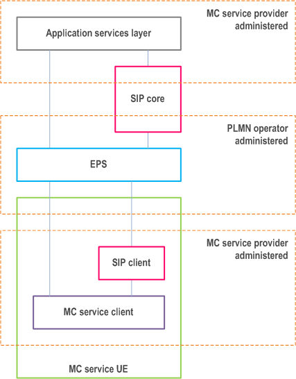
The MC service provider may require that all identities and signalling at the application services layer are hidden from the EPS, and may require identities and other sensitive information to be hidden from the PLMN operator administered part of the SIP core.
All authentication and authorisation mechanisms, including security roots, at the application services layer may need to be hidden from, and not available to, the PLMN operator.
9.2.2.1.6 PLMN operator administers SIP core with SIP identities administered by MC service provider p. 67
In this scenario, the PLMN operator administers the SIP core. However, the identities used by the SIP core (IMPI and IMPU) for MC service UEs served by the MC service provider are provided from the SIP database of the MC service provider.
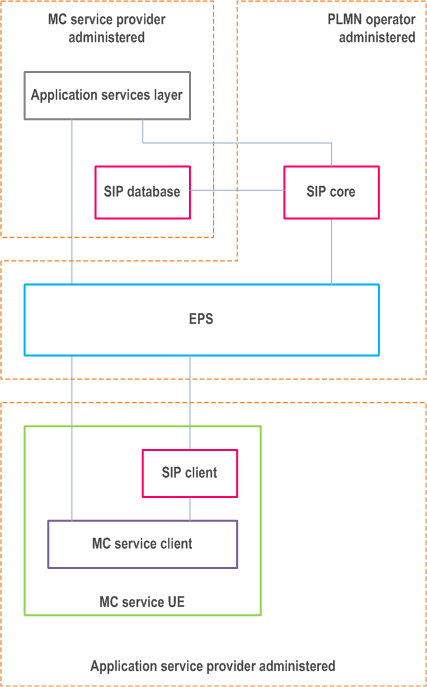
The MC service provider may require that all identities and signalling at the application services layer are hidden from the SIP core and EPS.
When required by the MC service provider, all authentication and authorisation mechanisms, including security roots, at the application services layer may need to be hidden from, and not available to, the PLMN operator.
The security roots (authentication keys) required for access to the signalling control plane are not available to the PLMN operator as these are held in the MC service provider's SIP database. However, derived parameters e.g. authentication vectors are provided to the SIP core to allow signalling control plane authentication to take place.
The HSS-IMS and HSS-EPS in this deployment scenario is across two different administrative domains, then IMS features such as, e.g., T-ADS (TS 23.237) related to service continuity between on-network and UE-to-network relay as in Annex B, NPLI (TS 23.228) related to lawful interception, and P-CSCF restoration (TS 23.380) are not supported.
9.2.2.2 MC service user database, SIP database and HSS p. 68
Figure 9.2.2.2-1 to Figure 9.2.2.2-4 show the possible deployment scenarios of the MC service user database and SIP database, including collocation with the HSS.
The MC service user database may be combined with an HSS in some deployment scenarios (e.g. when the MC service provider and the PLMN operator are part of the same trust domain).
The MC service user database may be a user data repository (UDR) in deployment scenarios when the UDC architecture is applied (see TS 23.335), in that case the MC service server and the configuration management server are assumed to be application front-ends and the Ud interface is used to access data from the repository.
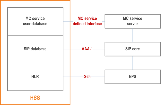
The HSS depicted in Figure 9.2.2.2-1 can be deployed either in the PLMN operator's network or the MC service provider's network.
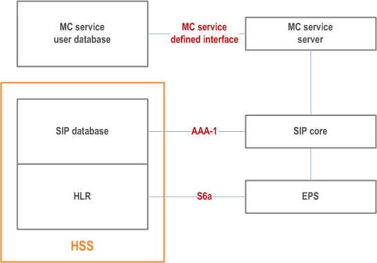
The MC service user database depicted in Figure 9.2.2.2-2 can be deployed in the PLMN operator's network or the MC service provider's network, and the HSS depicted in Figure 9.2.2.2-2 can be deployed in the same or different network to the MC service user database i.e. PLMN operator's network or the MC service provider's network.
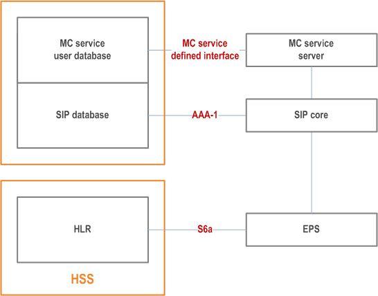
The MC service user database and SIP database depicted in Figure 9.2.2.2-3 can be deployed in the PLMN operator's network or the MC service provider's network, and the HSS depicted in Figure 9.2.2.2-3 can be deployed in the same or different network to the MC service user database i.e. PLMN operator's network or the MC service provider's network.
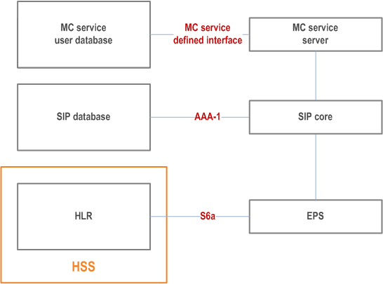
Each of the MC service user database, SIP database and HSS depicted in Figure 9.2.2.2-4 can be deployed in the same or different networks i.e. PLMN operator's network or the MC service provider's network.
9.2.2.3 Control of bearers by SIP core and MC service server p. 71
9.2.2.3.1 General p. 71
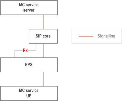
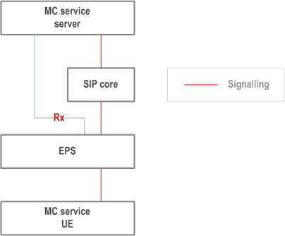
This subclause describes two different scenarios in which bearers are controlled by access to Rx by either the SIP core or the MC service server.
These may provide suitable models for each of the scenarios listed in subclause 9.2.2.1. However, there is no direct correlation of any of the scenarios described in this subclause to each of the scenarios described in subclause 9.2.2.1.
9.2.2.3.2 Control of bearers by SIP core p. 71
In this scenario, bearer control is performed by the SIP core alone, as shown in Figure 9.2.2.3.2-1 below.
9.2.2.3.3 Control of bearers by MC service server p. 71
In this scenario, bearer control is performed by the MC service server alone, as shown in Figure 9.2.2.3.3-1 below.
9.3 Architecture model for off-network operations p. 72
9.3.1 Off-network architectural model diagram p. 72
Figure 9.3.1-1 shows the off-network architectural model for the MC system solution for inter-UE communication, where no relay function is used.

Figure 9.3.1-2 shows the off-network architectural model for the MC system solution for configuration management and group management.
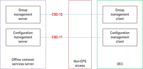
The offline common services server could be the same entity (or set of entities) as the common services core. In this case the configuration management server shall not configure to the same user on the same UE, with parameters provisioned by offline and online configuration simultaneously. The configuration management server shall not configure to the same user on the same UE for the same parameters by using CSC-11 and CSC-4 reference points simultaneously.
The entities within this model are described in the following subclauses and a full functional model is given in subclause 7.3.2.
9.3.2 UE 3 p. 72
The UE 3 is a UE using ProSe and supporting application(s) related to off-network MC service, and is composed of the following functional entities:
- for MC services, MC service clients as described in subclause 7.4.2.3.1 with relevant application functions of the specific MC service defined in the corresponding MC service TS;
- for signalling control, a signalling user agent as described in subclause 7.4.3.1.1;
- for configuration management, a configuration management client as described in subclause 7.4.2.2.1; and
- for group management, a group management client as described in subclause 7.4.2.2.3.
9.3.3 UE 4 p. 73
The UE 4 represents one or more UEs with the same functionality as UE 3.
9.3.4 Offline common services server p. 73
The offline common services server supports configuration applications related to MC service, and is composed of the following functional entities:
- for configuration management, a configuration management server as described in subclause 7.4.2.2.2; and
- for group management, a group management server as described in subclause 7.4.2.2.4.